
Closed free surface slotting blasting method capable of improving blasting efficiency

A free and efficient technology, applied in blasting, earth cube drilling, mining equipment, etc., can solve problems such as large clamping effect, single free surface, complex working environment, etc., to improve cutting efficiency, reduce consumption, and improve construction safe effect

Active Publication Date: 2020-06-19
ANHUI UNIV OF SCI & TECH
View PDF10 Cites 0 Cited by
  • Summary
  • Abstract
  • Description
  • Claims
  • Application Information

AI Technical Summary

Problems solved by technology

[0002] In the mining of underground mineral resources such as coal, when the hardness coefficient of the rock roadway is f>7, the mining method basically adopts blasting excavation. In the blasting tunneling of the roadway, the cutting effect directly determines the cycle footage. , there is only a single free surface, the clamping effect is large, and the general cutting effect is not ideal

Method used


Image

  • Closed free surface slotting blasting method capable of improving blasting efficiency
  • Closed free surface slotting blasting method capable of improving blasting efficiency
  • Closed free surface slotting blasting method capable of improving blasting efficiency

Examples


Embodiment 1

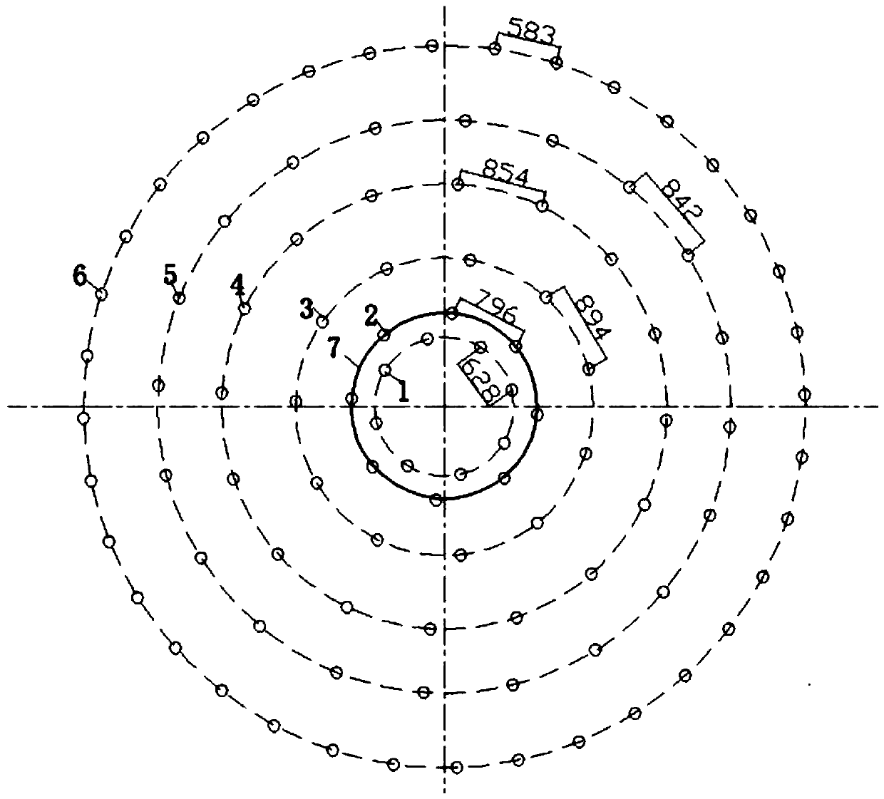
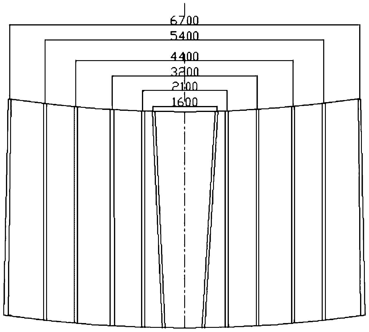
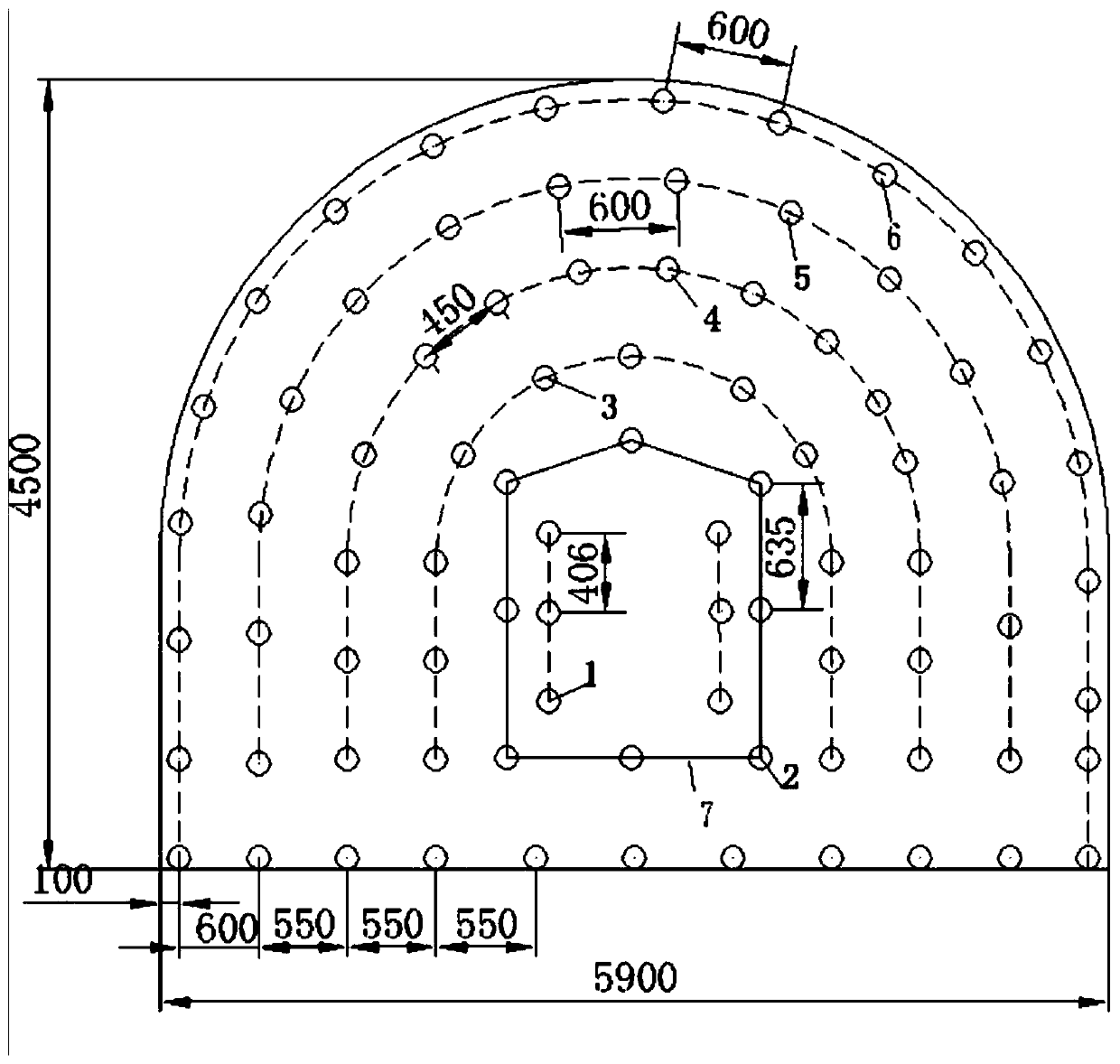
[0044] figure 1 and figure 2 The vertical shaft blast hole layout based on the closed free surface cut is given, image 3 and Figure 4 The layout of blastholes in level lanes based on closed free surface cuts is given, including cut holes 1, cut holes 2, auxiliary holes 3 in the first circle, auxiliary holes 4 in the second circle, auxiliary holes 5 in the third circle, peripheral holes 6 and closed free surface 7.

Embodiment 2

[0046] refer to Figure 5 , 6 , for use when the lithology is relatively hard or poor. On the basis of Example 1, an empty hole 8 is arranged between the two cutting holes 2 .

Embodiment 3

[0048] Figure 7 A schematic diagram of a blasting tube with control over the direction of crack propagation is given, including an explosive cavity 9 filled with explosives, a cavity 10 equipped with wave-stopping materials such as rubber pads and soft cloth, and an energy-dissipating joint 11 with an energy-dissipating joint angle 12 of 60° .


PUM


Abstract

The invention discloses a closed free surface slotting blasting method capable of improving blasting efficiency, and belongs to the technical field of mining construction. The closed free surface slotting blasting method comprises the following steps that a slotting hole, a cutting hole, a first auxiliary hole, a second auxiliary hole, a third auxiliary hole and peripheral holes are sequentially arranged on a working surface, and a blasting pipe capable of controlling a crack propagation direction is prepared; explosives are loaded into the blasting pipe firstly, then the blasting pipe loadedwith the explosives is placed into the cutting hole, and the cutting direction of the blasting pipe is adjusted through a tamping bar so that an annular closed free face can be formed in the cutting direction of the cutting hole; common cartridges are sequentially loaded into the blast holes, and the blast holes are sequentially blocked with stemming; and finally, millisecond detonation is adopted. According to the closed free surface slotting blasting method, the cutting hole is detonated before the slotting hole, the closed annular free surface is formed around the slotting hole, and the slotting effect can be improved by the closed annular free surface so that the overall explosive consumption can be reduced, the harm and cost of explosive explosion to surrounding rock masses and adjacent structures are reduced, and the blasting efficiency and the construction safety are improved.

Description

technical field [0001] The invention relates to a blasting method, in particular to a closed free surface cutting blasting method for improving blasting efficiency, which belongs to the technical field of mining construction. Background technique [0002] In the mining of underground mineral resources such as coal, when the hardness coefficient of the rock roadway is f>7, the mining method basically adopts blasting excavation. In the blasting tunneling of the roadway, the cutting effect directly determines the cycle footage. , there is only a single free surface, the clamping effect is large, and the general cutting effect is not ideal. Contents of the invention [0003] The main purpose of the present invention is to provide a closed free surface cut blasting method that improves blasting efficiency in order to solve the deficiencies of the prior art. [0004] The purpose of the present invention can be achieved by adopting the following technical solutions: [0005]...

Claims


Application Information

Patent Timeline
IPC IPC(8): F42D1/00F42D1/08F42D3/04E21D9/00
CPCF42D1/00F42D1/08F42D3/04E21D9/006
Inventor 苏洪龚悦李凯汪灿冯伟曹帅马亮杰吴学鹏王馨
Owner ANHUI UNIV OF SCI & TECH
Learn More