Bulk acoustic wave resonator provided with insertion structure and temperature compensation layer, filter and electronic equipment

A bulk acoustic wave resonator, resonator technology, applied in the direction of electrical components, impedance networks, etc., can solve the problems of resonance frequency drift, limit composite insertion resonators, etc.

Pending Publication Date: 2020-06-19
TIANJIN UNIV +1
View PDF2 Cites 13 Cited by
  • Summary
  • Abstract
  • Description
  • Claims
  • Application Information

AI Technical Summary

Problems solved by technology

[0004] However, as the operating temperature changes, figure 1 The resonant frequency of the shown re...

Method used


Image

  • Bulk acoustic wave resonator provided with insertion structure and temperature compensation layer, filter and electronic equipment
  • Bulk acoustic wave resonator provided with insertion structure and temperature compensation layer, filter and electronic equipment
  • Bulk acoustic wave resonator provided with insertion structure and temperature compensation layer, filter and electronic equipment

Examples


Embodiment Construction

[0047]The technical solutions of the present invention will be further specifically described below through the embodiments and in conjunction with the accompanying drawings. The following description of the embodiments of the present invention with reference to the accompanying drawings is intended to explain the general inventive concept of the present invention, but should not be construed as a limitation of the present invention.

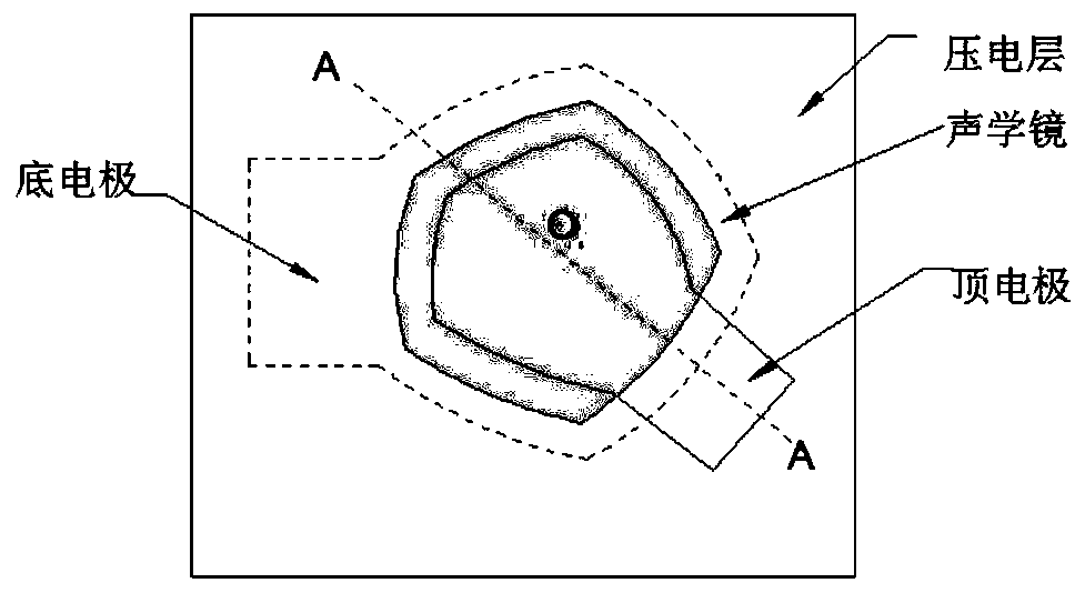
[0048] figure 2 is a schematic top view of a bulk acoustic wave resonator according to an exemplary embodiment of the present invention. Such as figure 2 As shown, the bulk acoustic wave resonator includes an acoustic mirror, a bottom electrode, a piezoelectric layer, and a top electrode. The overlapping area of ​​the above four components in the thickness direction of the resonator is defined as the effective area of ​​the resonator. The letter O represents the center of the resonator.

[0049] Figure 3-5 for different embodiments based ...


PUM


Abstract

The present invention relates to a bulk acoustic wave resonator, and the resonator comprises a substrate; an acoustic mirror; a bottom electrode; a top electrode; wherein an overlapped area of the acoustic mirror, the bottom electrode, the piezoelectric layer and the top electrode in the thickness direction of the substrate is an effective area of the resonator; wherein a composite insertion structure arranged along the edge of the effective region is arranged in the piezoelectric layer, the composite insertion structure comprises a first insertion layer and a second insertion layer, at leastone part of the first insertion layer is overlapped with the effective region in a top view of the resonator, and the first insertion layer is at least partially overlapped with the second insertion layer in the top view of the resonator, wherein the first insertion layer is made of a metal material and the second insertion layer is made of air or a dielectric material, or the first insertion layer is made of a dielectric material and the second insertion layer is made of air, in a top view of the resonator, at least one part of the temperature compensation layer is located in the effective area, and the temperature compensation layer is made of a material opposite to the piezoelectric layer in frequency temperature coefficient. The invention also relates to a filter and an electronic device.

Description

technical field [0001] Embodiments of the present invention relate to the field of semiconductors, and in particular to a bulk acoustic wave resonator, a filter, and an electronic device having one of the above components. Background technique [0002] Bulk acoustic wave filters have the advantages of low insertion loss, high square factor, and high power capacity. Therefore, they are widely used in contemporary wireless communication systems and are important components that determine the quality of radio frequency signals entering and leaving the communication system. The performance of a bulk acoustic wave filter is determined by the bulk acoustic wave resonator that constitutes it. For example, the resonant frequency of the bulk acoustic wave resonator determines the operating frequency of the filter, the effective electromechanical coupling coefficient determines the bandwidth of the filter, and the quality factor determines the filter insertion. loss. When the filter ...

Claims


Application Information

Patent Timeline
IPC IPC(8): H03H9/02H03H9/15H03H9/17H03H9/13
CPCH03H9/02228H03H9/02244H03H9/15H03H9/17H03H9/13H03H2009/02503H03H2009/155
Inventor 杨清瑞庞慰张孟伦
Owner TIANJIN UNIV
Why Eureka
Try Eureka