5G communication signal induction device

A technology for sensing equipment and communication signals, applied in the field of 5G communication signal sensing equipment, can solve problems affecting signal induction strength, weak support points, unstable connections, etc., and achieve the effect of reducing dust accumulation and contact friction

Inactive Publication Date: 2020-06-19
泉州早稻云信息科技有限公司
View PDF0 Cites 0 Cited by
  • Summary
  • Abstract
  • Description
  • Claims
  • Application Information

AI Technical Summary

Problems solved by technology

[0003] The existing small 5G communication signal sensing equipment is generally installed outdoors, and it mainly uses the antenna monitoring sensor on the fin tube to realize the signal induction connection. Because it is used outdoors, outdoor insects and some birds, especially, Birds are large in size. When birds stand on the wing tubes, the mechanically connected wing tubes are accompanied by the impact force generated when the birds take off. The support points of the mechanically connected wing tubes are relatively fragile. Shaking, even the unstable connection will not only affect the signal induction strength, but also cause the finned tube to fall and damage

Method used


Image

  • 5G communication signal induction device
  • 5G communication signal induction device
  • 5G communication signal induction device

Examples


Embodiment 1

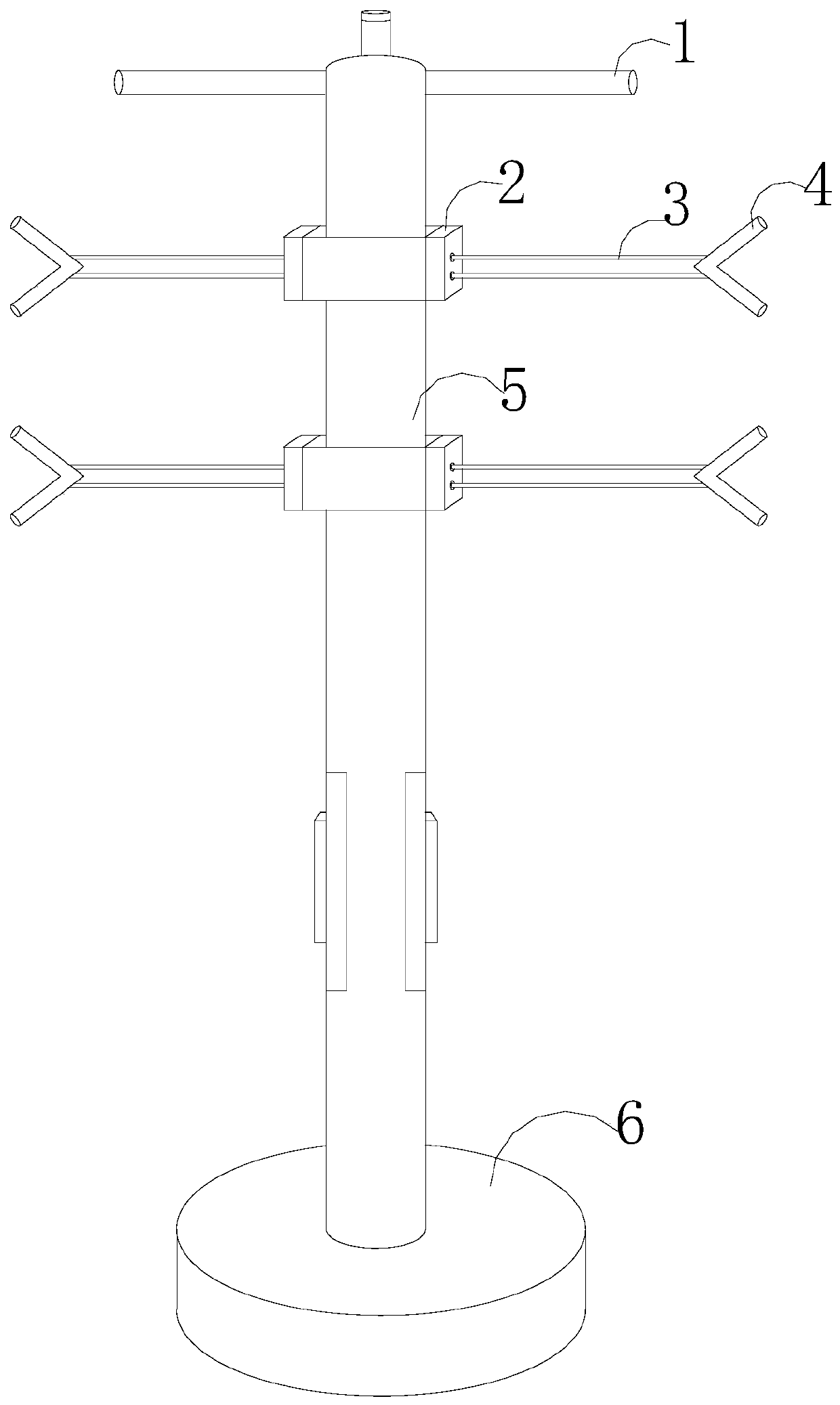
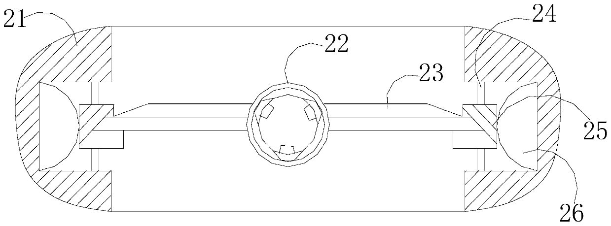
[0031] like Figure 1-Figure 3 As shown, the present invention provides a 5G communication signal sensing device, the structure of which includes a support rod 1, a fin tube mounting seat 2, a fin tube 3, an antenna monitoring sensor 4, a pillar 5, and a base 6, and the support rod 1 is welded on The top of the pillar 5, the finned tube 3 is provided with four, uniformly fixed on the pillar 5 by the finned tube mounting seat 2, the antenna monitoring sensor 4 is installed on the end of the finned tube 3 relative to the pillar 5, the pillar 5 is vertically connected to the base 6, and the finned tube mounting seat 2 is provided with a support groove 21, a finned tube interface 22, a deformation bridge 23, a spring 24, a bridge interface 25, and an extruded part 26, and the left and right sides of the support groove 21 The end is provided with a mounting groove with a concave structure, and the mounting groove is provided with an extrusion part 26, a bridge interface 25 and a sp...

Embodiment 2

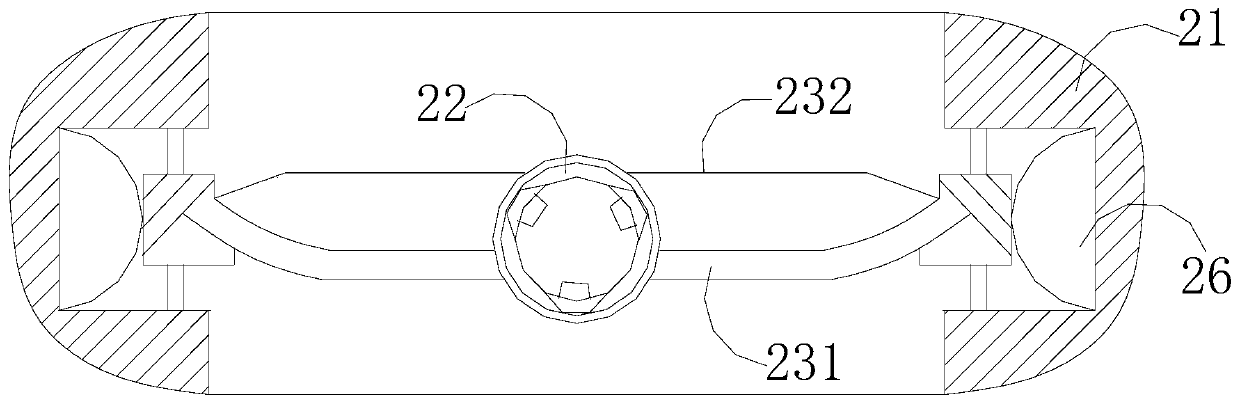
[0033] like Figure 4-Figure 6As shown, according to the fin tube interface with a buffer function described in Embodiment 1, the fin tube interface 22 includes a clip angle 221, a receiving plate 222, a clip slot 223, and an expansion ear 224, and the clip angle 221 is inserted into the fin tube. At the bottom of the tube 3, the clamping angle 221 and the clamping groove 223 are fixed in a rotationally fitted manner, the clamping groove 223 is arranged on the receiving plate 222, and two More than one expansion ear 224, the bridge interface 25 is provided with a soft touch layer 25a and a hard layer 25b, wherein the hard layer 25b is connected to the deformation bridge 23, the soft touch layer 25a is a sponge layer, and the extruded part 26 is composed of There are deformation balls 261, swing rods 262, and center rollers 263. The deformation balls 261 are in a semicircular structure. The swing rods 262 are mechanically connected by the center rollers 263. One end accepts the...


PUM


Abstract

The invention discloses a 5G communication signal induction device. The device structurally comprises a supporting rod, a finned tube mounting seat, a finned tube, an antenna monitoring sensor, a supporting column and a base, the support rod is welded at the top of the strut; four finned tubes are arranged, the finned tubes are uniformly fixed on the support columns through the finned tube mounting seats; an antenna monitoring sensor is mounted at one end, opposite to the strut, of the finned tube; the supporting column is vertically connected to the base. The finned tube mounting base is provided with a supporting groove, a finned tube connector, a deformation bridge, a spring, a bridge connector and an extrusion piece. According to the invention, the finned tube interface and the deformation bridge are matched with the bridge interface and the spring; when the bearing weight exceeds a set value, the finned tube connector is arranged on the deformation bridge; by changing the gap between the connecting pull rod and the fixing rod and further combining the springs matched with the bridge connectors at the two ends of the deformation bridge, the finned tube connector with the buffering function is achieved, and the situation that the joint of the finned tube connector and the finned tube is broken and damaged due to gravity impact caused by bird parking on the finned tube is avoided.

Description

technical field [0001] The invention relates to the field of 5G communication equipment, in particular, it is a 5G communication signal sensing equipment. Background technique [0002] 5G is the fifth generation of mobile communication technology, and it is also an extension of 4G. For wireless mobile networks including 5G mobile communication technology, the improvement of network service capabilities will inevitably be carried out simultaneously; first, the introduction of advanced After wireless transmission technology, the utilization rate of network resources will be increased by at least 10 times on the basis of 4G mobile communication technology; It is expected that the throughput rate of the entire wireless network system will increase by about 25 times; thirdly, in-depth exploration of more advanced frequency resources, such as visible light, millimeter wave, high frequency band, etc., will make the future wireless mobile communication resources expand compared with...

Claims


Application Information

Patent Timeline
Patent Type & Authority Applications(China)
IPC IPC(8): H04W88/08
CPCH04W88/08
Inventor 林志鹏
Owner 泉州早稻云信息科技有限公司
Why Eureka
Try Eureka