
Millimeter wave antenna structure, microwave rotary radar and movable platform

A millimeter wave antenna and mobile platform technology, which is applied to antennas, antennas, antenna arrays and other directions suitable for movable objects, and can solve problems such as complex structure, difficult processing, and complex data processing.

Inactive Publication Date: 2020-06-19
SZ DJI TECH CO LTD
View PDF14 Cites 5 Cited by
  • Summary
  • Abstract
  • Description
  • Claims
  • Application Information

AI Technical Summary

Problems solved by technology

[0003] However, the above-mentioned schemes all have some unsatisfactory points. For example, for scheme 1, the antenna lens is a low-loss, high-dielectric constant material, which is difficult to process and has low precision, and the size and weight of the lens are quite large; scheme 2, similar to the lens antenna , the profile and weight of the reflective surface are large, and it needs to occupy a lot of space; scheme 3, each array element of the phased array needs T / R (transmitting / receiving) components, the structure is complex, the cost is high, and it is generally used for military purposes; For option 4, the mechanical structure itself is complex, high cost, and low reliability. For option 5, the multi-transmission and multi-reception antenna system in the form of MIMO is complex, and the transmission needs to be switched in time, and the corresponding data processing is very complicated.

Method used


Image

  • Millimeter wave antenna structure, microwave rotary radar and movable platform
  • Millimeter wave antenna structure, microwave rotary radar and movable platform
  • Millimeter wave antenna structure, microwave rotary radar and movable platform

Examples


Embodiment Construction

[0055] In order to make the objects, technical solutions and advantages of the present invention more apparent, exemplary embodiments according to the present invention will be described in detail below with reference to the accompanying drawings. Apparently, the described embodiments are only some embodiments of the present invention, rather than all embodiments of the present invention, and it should be understood that the present invention is not limited by the exemplary embodiments described here. Based on the embodiments of the present invention described in the present invention, all other embodiments obtained by those skilled in the art without creative efforts shall fall within the protection scope of the present invention.

[0056]In the following description, numerous specific details are given in order to provide a more thorough understanding of the present invention. It will be apparent, however, to one skilled in the art that the present invention may be practiced...


PUM


Abstract

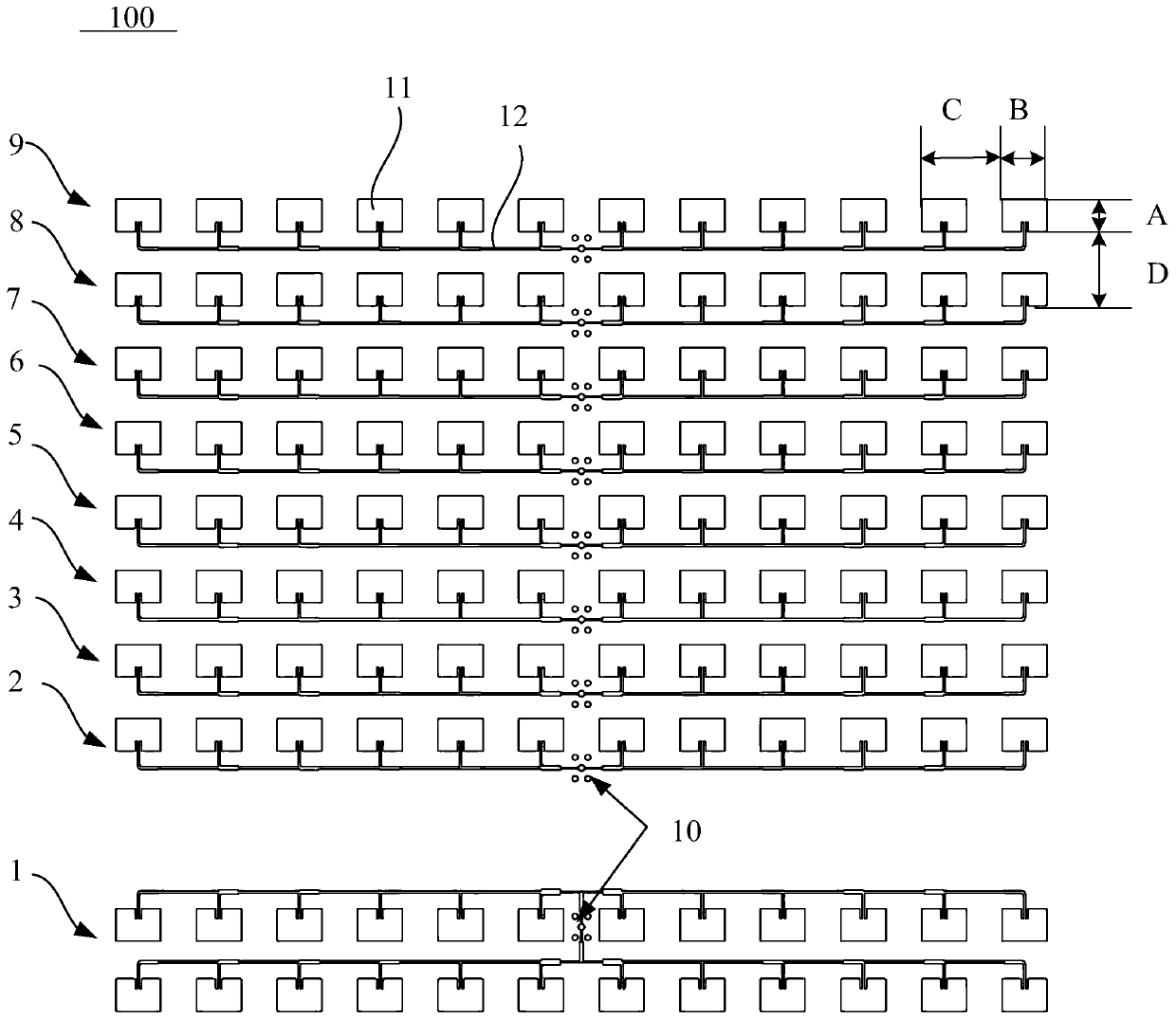
The invention provides a millimeter wave antenna structure (100), a microwave rotary radar (200) and a movable platform (300). The millimeter wave antenna structure (100) comprises: a substrate (101);and a plurality of antenna arrays formed on a first side surface of the substrate (101), wherein the antenna arrays comprise at least one transmitting antenna array (1) and a plurality of receiving antenna arrays (2, 3, 4, 5, 6, 7, 8, 9), and the at least one transmitting antenna array (1) and the plurality of receiving antenna arrays (2, 3, 4, 5, 6, 7, 8, 9) are arranged in parallel and at intervals; each receiving antenna array (2, 3, 4, 5, 6, 7, 8, 9) comprises at least one column of microstrip patch units (11), and each column of microstrip patch units (11) comprises two groups of microstrip patch units (11) which are symmetrically distributed; and the distance between every two adjacent receiving antenna arrays ranges from 6.0 mm to 15.0 mm. The millimeter wave antenna structure (100), the microwave rotary radar (200) and the movable platform (300) can realize a large angle measurement range and a large angle measurement resolution ratio in a small size, and actual use requirements are met.

Description

technical field [0001] The present invention generally relates to the technical field of antenna structures, and more particularly relates to a millimeter wave antenna structure, a microwave rotating radar and a movable platform. Background technique [0002] With the development of millimeter-wave devices, millimeter-wave radars can be miniaturized and integrated. With the same antenna diameter, millimeter-wave radars can obtain narrower antenna beams and higher antenna gain, which can improve the angle measurement of radars. High resolution and angle measurement accuracy, and it is beneficial to resist electronic interference, clutter interference and multipath reflection interference. The existing antenna schemes to achieve large-scale detection mainly include the following types: 1. Lens antenna, which uses the lens to gather the energy radiated by the feed source to form a sharp beam. When multiple feed sources are set near the focus of the lens, it is convenient Corre...

Claims


Application Information

Patent Timeline
Patent Type & Authority Applications(China)
IPC IPC(8): H01Q1/12H01Q1/27H01Q1/28H01Q1/32H01Q1/38H01Q21/06G01S7/02
CPCG01S7/02G01S7/024H01Q1/12H01Q1/27H01Q1/285H01Q1/3233H01Q1/38H01Q21/065H01Q1/32
Inventor 唐照成贺翔王春明孙维忠
Owner SZ DJI TECH CO LTD
Learn More