Forming machine tool for rice-milling grinding wheel

A molding and machine tool technology, applied in the direction of large fixed members, metal processing machinery parts, feeding devices, etc., can solve the problems of low production efficiency and low product quality consistency, reduce labor intensity, avoid processing errors, and improve product accuracy and the effect of efficiency

Pending Publication Date: 2020-06-23
湖北省鄂州市天元砂辊有限责任公司
0 Cites 0 Cited by

AI-Extracted Technical Summary

Problems solved by technology

[0003] The main purpose of the present invention is to propose a forming machine tool for rice milling wheel, aiming to solve the problem that the existing forming machine tool fo...

Abstract

The invention discloses a forming machine tool for a rice-milling grinding wheel. The forming machine tool for the rice-milling grinding wheel comprises a machine seat, a tool rest assembly, a workingdriving device and a tool rest driving device; a working table which can rotate along a vertical axis and slide horizontally is disposed on the machine seat, the tool rest assembly is installed on the machine seat vertically slideably and used for machining and forming of a plane, an inner hole and an outer circle of a workpiece on the working table; the working table driving device is used for driving the working table to rotate and horizontally slide; and the tool rest driving device is used for driving the tool rest assembly to slide up and down. In the technical scheme provided by the invention, an existing manual mode is abandoned, the forming machine tool for the rice-milling grinding wheel adopts a new numerical control technology and a new machine tool structure, machining and forming of the outer circle, the inner hole and the end surface of the rice-milling grinding wheel can be achieved by additionally arranging a combined tool structure, multiple procedures are completed once, the machining errors caused by repeated clamping are avoided, the product accuracy and the efficiency are improved, and the labor intensity of people is relieved.

Application Domain

Feeding apparatusLarge fixed members

Technology Topic

Machine toolKnife holder +5

Image

  • Forming machine tool for rice-milling grinding wheel
  • Forming machine tool for rice-milling grinding wheel
  • Forming machine tool for rice-milling grinding wheel

Examples

  • Experimental program(1)

Example Embodiment

[0031] The technical solutions in the embodiments of the present invention will be clearly and completely described below in conjunction with the accompanying drawings in the embodiments of the present invention. Obviously, the described embodiments are only a part of the embodiments of the present invention, rather than all the embodiments. Based on the embodiments of the present invention, all other embodiments obtained by those of ordinary skill in the art without creative work shall fall within the protection scope of the present invention.
[0032] It should be noted that if there is a directional indication involved in the embodiment of the present invention, the directional indication is only used to explain the relative positional relationship, movement, etc. between the components in a specific posture. If the specific posture changes , The directional indicator changes accordingly.
[0033] In addition, if there are descriptions related to "first", "second", etc. in the embodiments of the present invention, the descriptions of "first", "second", etc. are only used for descriptive purposes, and cannot be understood as instructions or implications Its relative importance or implicitly indicates the number of technical features indicated. Therefore, the features defined with "first" and "second" may explicitly or implicitly include at least one of the features. In addition, the meaning of "and/or" in the full text includes three parallel schemes. Taking "A and/or B" as an example, it includes scheme A, scheme B, or schemes in which both A and B meet. In addition, the technical solutions between the various embodiments can be combined with each other, but it must be based on what can be achieved by a person of ordinary skill in the art. When the combination of technical solutions is contradictory or cannot be achieved, it should be considered that such a combination of technical solutions does not exist. , Is not within the protection scope of the present invention.
[0034] At present, most of the existing rice milling wheel forming machine tools are manual mode operation machine tools, which mainly drive the processing spindle feed through the transmission handle, and complete the plane of the rice milling wheel through the rotation of the spindle and the rotation of the worktable, but only the plane can be processed. Need personnel to work uninterruptedly. This type of equipment cannot meet the current trend of increasingly high-speed development, the production efficiency is low, and the consistency of product quality is not high.
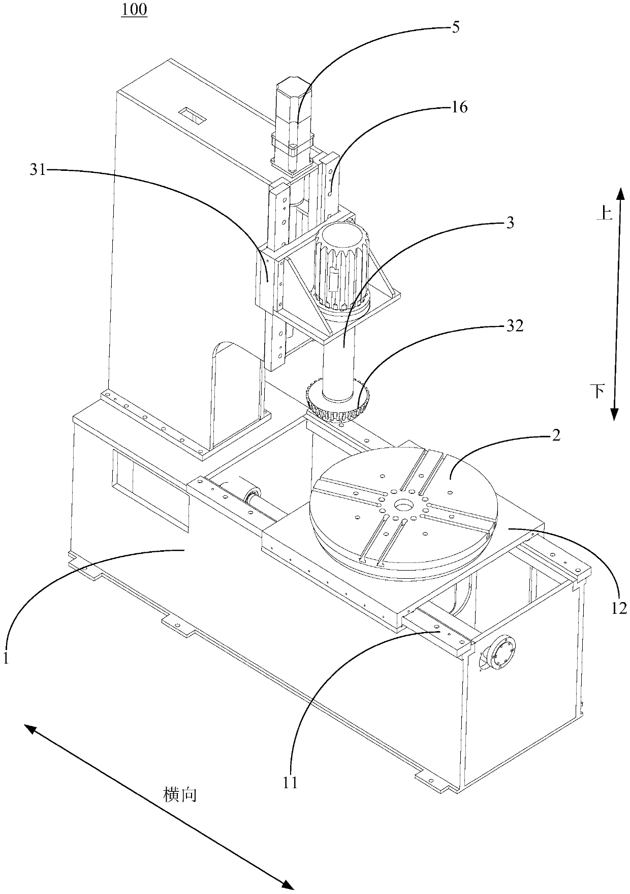
[0035] In view of this, the present invention provides a forming machine tool for rice milling wheels, Figure 1 to Figure 8 An embodiment of a forming machine tool for rice milling wheels provided by the present invention.
[0036] Specifically, please refer to Figure 1 to Figure 3 The forming machine tool 100 for rice milling wheels includes a machine base 1, a tool holder assembly 3, a table driving device 4, and a tool holder driving device 5. The machine base 1 is provided with a vertical axis capable of rotating and A horizontally sliding worktable 2, the worktable 2 is used to carry workpieces, and the tool holder assembly 3 is slidably mounted on the machine base 1 up and down to realize the plane of the workpiece on the worktable 2 , The inner hole and the outer circle are processed and formed, the table driving device 4 and the tool rest driving device 5 are both arranged on the machine base 1, and the table driving device 4 is used to drive the working table 2 Rotating and sliding horizontally, the tool holder driving device 5 is used to drive the tool holder assembly 3 to slide up and down.
[0037] In the technical solution provided by the present invention, the existing manual mode is abandoned. The forming machine tool 100 for rice milling wheels applies new numerical control technology and a new machine tool structure. By adding a combined tool structure, rice milling can be realized. The outer circle, inner hole and end face of the grinding wheel are processed and formed in multiple processes at one time to avoid processing errors caused by multiple clamping, improve product accuracy and efficiency, and reduce labor intensity.
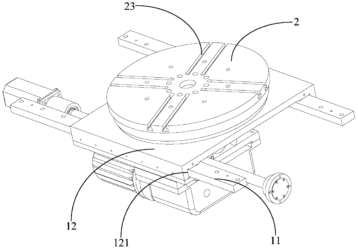
[0038] Generally, the molding machine tool 100 for rice milling wheels further includes a control device (not shown in the figure, for example, the control device may be a Siemens 808D system), and the control device is electrically connected to the tool holder The assembly 3, the table driving device 4, and the tool rest driving device 5. After fixing the rice milling wheel on the worktable 2 (specifically, please refer to figure 2 In this embodiment, the worktable 2 is arranged in a disc shape, and a plurality of sliding chutes 23 extending in the radial direction are provided on the worktable 2 at intervals along the circumferential direction. A tooling fixture is installed to fix the rice milling wheel on the worktable 2), the molding machine tool 100 for rice milling wheel controls the tool holder assembly 3 and the worktable driving device 4 through the control device Form a complete processing system with the tool holder driving device 5, replace the appropriate tool combination to realize the shaping process of the plane, inner hole and outer circle of the rice milling wheel, so as to realize the plane, inner hole and outer circle of the rice milling wheel One-time molding to improve product accuracy and efficiency.
[0039] The workbench 2 can slide horizontally, specifically, please refer to Figure 1 to Figure 3 In this embodiment, the workbench 2 is capable of lateral sliding, the tool holder assembly 3 and the workbench 2 are horizontally arranged on the machine base 1, and the tool holder assembly 3 is located in the Above the workbench 2. In this way, by limiting the specific way of horizontal sliding of the worktable 2 and the positional relationship between the tool holder assembly 3 and the worktable 2, the overall structure of the forming machine tool 100 for rice milling wheels is changed. It is compact, and it is not easy to cause interference between the worktable 2 and the tool holder assembly 3.
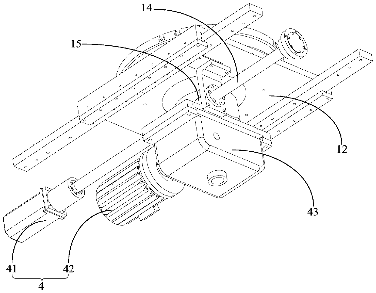
[0040] Further, see Figure 1 to Figure 3 In this embodiment, the machine base 1 is provided with a transverse guide rail 11 extending in the transverse direction, the transverse guide rail 11 is provided with a sliding seat 12 that can slide transversely, and the workbench 2 is capable of moving up and down. The axis is rotatably mounted on the sliding seat 12. The table driving device 4 includes a transverse drive unit 41 and a rotation drive unit 42. The transverse drive unit 41 is used to drive the sliding seat 12 on the transverse guide rail 11. The rotary drive unit 42 is used to drive the worktable 2 to rotate on the sliding seat 12. Through the structure of the sliding seat 12, the rotation and lateral sliding of the worktable 2 can be separately controlled.
[0041] Go further, see figure 2 with image 3 In this embodiment, the bottom of the sliding seat 12 is transversely provided with a transverse guide groove 121, and the transverse guide groove 121 and the transverse guide rail 11 form a guiding fit in the transverse direction. The cooperation between the lateral guide groove 121 and the lateral guide rail 11 can play a role in guiding the sliding seat 12.
[0042] See Figure 4 In this embodiment, the sliding seat 12 is provided with a slewing support 13 which abuts against the bottom surface of the worktable 2 and is used for slewing support of the worktable 2. The arrangement of the rotary support 13 facilitates the smooth rotation of the worktable 2.
[0043] Further, see Figure 4 to Figure 6 In this embodiment, a first boss 122 is protrudingly provided on the sliding seat 12 and located on the periphery of the slewing support member 13, and the bottom surface of the work table 2 is protruding from the first boss 122 The second boss 21, the first boss 122 and the second boss 21 are both arranged in a ring shape extending along the rotation direction of the worktable 2, and are used to form a accommodating accommodating member 13 Cavity 24; the end surface of the free end of the first boss 122 is provided with a plurality of first ring-shaped ribs 123 spaced apart, and the end surface of the free end of the second boss 21 corresponds to the first ring-shaped boss The ribs 123 are provided with multiple rings of second annular ribs 211 at intervals, and the multiple rings of first annular ribs 123 and the multiple rings of second annular ribs 211 are interlocked to prevent dust from entering the containing cavity twenty four. In this way, through the formation of the accommodating cavity 24 and the cooperation between the first ring-shaped ribs 123 and the second ring-shaped ribs 211, a better dust-proof effect can be achieved.
[0044] Further, see Figure 4 with Figure 5 In this embodiment, the bottom surface of the workbench 2 is provided with the guide protrusions 21, and the top surface of the sliding seat 12 is provided with a plurality of protrusions extending along the rotation direction of the workbench 2 at intervals. Rib 123, the guide groove 122 is formed between two adjacent ribs 123, the bottom surface of the worktable 2 and the inner side of the plurality of ribs 123 are provided with a rotating support 13, and the rotating The support 13 abuts against the bottom surface of the workbench 2 and is used to support the workbench 2. The arrangement of the rotary support 13 facilitates the smooth rotation of the worktable 2.
[0045] The lateral drive unit 41 can drive the sliding seat 12 to slide laterally on the lateral guide rail 11. The arrangement of the lateral drive unit 41 may not be particularly limited. For details, please refer to image 3 In this embodiment, the machine base 1 is provided with a first ball screw 14 arranged in a transverse direction, and the sliding seat 12 is provided with a first screw nut that cooperates with the first ball screw 14 15. The lateral drive unit 41 is a first drive motor connected to one end of the first ball screw 14.
[0046] Similarly, the rotation driving unit 42 can drive the worktable 2 to rotate on the sliding seat 12, and there is no special limitation on the arrangement of the rotation driving unit 42. For details, please refer to image 3 with Figure 4 In this embodiment, the bottom of the workbench 2 is provided with a main shaft 22 extending in the up and down direction, and the rotation driving unit 42 is a second driving motor arranged in a transverse direction. The transmission shaft of the second driving motor passes The reducer 43 is connected to the lower end of the main shaft 22.
[0047] See figure 1 with Figure 7 In this embodiment, the machine base 1 is provided with a vertical guide rail 16 extending in the up and down direction, and the tool holder assembly 3 includes a tool holder seat 31 that can be slidably mounted on the vertical guide rail 16 up and down. A vertical guide groove 311 penetrates through the tool holder seat 31 in the up and down direction, and the vertical guide groove 311 and the vertical guide rail 16 form a guide fit in the up and down direction. Through the cooperation of the vertical guide rail 16 and the vertical guide groove 311, the tool holder assembly 3 can be guided to slide.
[0048] The tool rest driving device 5 can drive the tool rest assembly 3 to slide up and down, and there is no special limitation on the setting method of the tool rest driving device 5. For details, please refer to figure 1 with Figure 7 In this embodiment, the machine base 1 is provided with a second ball screw 17 arranged in the up and down direction, and the tool holder assembly 3 is provided with a second screw that cooperates with the second ball screw 17 The rod nut 18, the tool post driving device 5 is a third driving motor connected to one end of the second ball screw 17.
[0049] The tool holder assembly 3 can realize the processing and shaping of the plane, inner hole and outer circle of the rice milling wheel on the worktable 2. For details, please refer to Figure 7 with Picture 8 In this embodiment, the tool holder assembly 3 includes a tool 32 capable of rotating along a vertical axis, and a tool driving device 33 for driving the tool 32 to rotate; wherein, the tool 32 includes a main body 321, The first blade portion 322 and the second blade portion 323. The main body 321 is connected to the cutter driving device 33 and is arranged in a downwardly facing disk shape. The first blade portion 322 is provided on the peripheral side of the main body 321, And there are a plurality of cutters 32 along the direction of rotation, the second blade portion 323 is disposed on the bottom surface of the main body 321, and the cutters 32 are disposed along the direction of rotation. The tool holder assembly 3 can realize the processing and shaping of the inner hole and the outer circle of the rice milling wheel through the first knife edge portion 322, and can realize the processing and shaping of the plane of the rice milling wheel through the second knife edge portion 323.
[0050] The above descriptions are only the preferred embodiments of the present invention, and do not limit the scope of the present invention. Under the concept of the present invention, equivalent structural transformations made by using the contents of the description and drawings of the present invention, or directly/indirectly applied to Other related technical fields are included in the scope of patent protection of the present invention.

PUM

no PUM

Description & Claims & Application Information

We can also present the details of the Description, Claims and Application information to help users get a comprehensive understanding of the technical details of the patent, such as background art, summary of invention, brief description of drawings, description of embodiments, and other original content. On the other hand, users can also determine the specific scope of protection of the technology through the list of claims; as well as understand the changes in the life cycle of the technology with the presentation of the patent timeline. Login to view more.

Similar technology patents

Aerospace-grade ball grid precision machining system

ActiveCN110520686BImprove processing efficiencyAvoid machining errors
Owner:SUZHOU KEAIJIA AUTOMATION TECH CO LTD

Milling machine fixture

PendingCN110561156AWide range of applicationsAvoid machining errors
Owner:UNIV OF JINAN

Security inspection machine and its conveying device

ActiveCN108602624BEasy to assembleAvoid machining errors
Owner:DONGGUAN ZKTECO ELECTRONICS TECH

Classification and recommendation of technical efficacy words

  • Avoid machining errors
  • Improve product accuracy and efficiency

Multi-variety-shared cam-type distribution punching progressive die

ActiveCN104148501Aavoid inertiaAvoid machining errors
Owner:CANGZHOU ORBON ELECTRICAL & MECHANICAL PROD MAKING

Milling method of graphene aluminum-based composite material

ActiveCN105290470AAvoid machining errorsHigh precision milling
Owner:CHENGDU AEROSPACE JINGCHENG SCI & TECH CO LTD

Electric discharge machining jig and method

PendingCN110560812AAvoid machining errorsGuarantee processing quality
Owner:GREE ELECTRIC APPLIANCES WUHAN +1

Part precision machining device for high-end equipment manufacturing

PendingCN114454057AAvoid machining errorsHigh precision
Owner:南京智徐鑫科技有限公司

Multi-color transfer printing automation equipment

PendingCN113978114AImprove product accuracy and efficiency
Owner:SHENZHEN SAPPHIRE AUTOMATION EQUIP
Why Eureka
Try Eureka