Flaky inductance tin soldering equipment

A technology of soldering and inductance, which is applied in the field of chip inductor soldering equipment, can solve problems such as unfavorable soldering, impact on growth, and chip inductors cannot be cooled quickly, and achieve the effect of improving operation safety

Pending Publication Date: 2020-06-23
张永成
View PDF7 Cites 1 Cited by
  • Summary
  • Abstract
  • Description
  • Claims
  • Application Information

AI Technical Summary

Problems solved by technology

[0003] 1) By electromagnetically absorbing the sheet inductance to be soldered, because the magnetic force can be attracted by objects, it will cause too much absorption of the sheet inductance to be soldered, which is not conducive to the progress of soldering;
[0004] 2) During the soldering process, smoke will be produced, and the smoke contains slightly toxic gas. If the operator inhales the smoke, it will cause failure of the lungs, liver, kidneys, etc., which will affect fertility and cause great harm to human health. In addition, smog can also cause air pollution;
[0005] 3) Chip inductors after soldering cannot be cooled quickly, which will affect the efficiency of soldering

Method used


Image

  • Flaky inductance tin soldering equipment
  • Flaky inductance tin soldering equipment
  • Flaky inductance tin soldering equipment

Examples


Embodiment 1

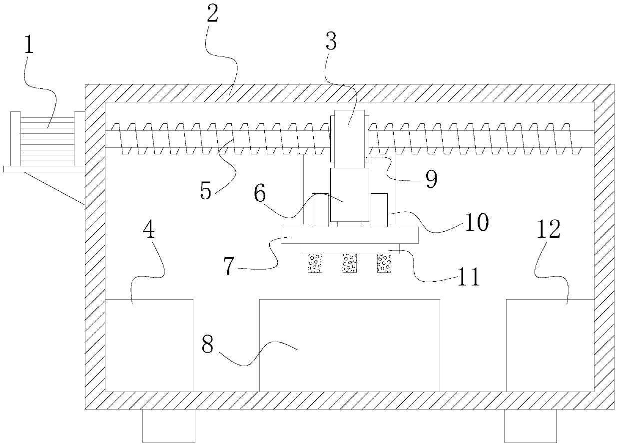
[0036] see Figure 1-4, the present invention provides a technical solution for sheet-shaped inductance soldering equipment: its structure includes a high-efficiency energy-saving motor 1, a body 2, a mounting sleeve 3, a finished product placement cylinder 4, a screw rod 5, a hydraulic cylinder 6, a cooling device 7, a tin furnace 8, Nut pair 9, smog absorption and purification device 10, electromagnetic panel 11, and a tube 12 for placing parts to be soldered. A tin furnace 8 is fixed in the center of the inner bottom surface of the body 2. One side of the tin furnace 8 is provided with a finished product placement tube 4. One side is provided with a tube 12 for placing the parts to be soldered, and the tube 4 for placing the finished product and the tube 12 for placing the parts to be soldered are all connected to the inner wall of the body 2, and the tube 4 for the finished product can place the chip inductor that has been soldered. The setting of the solder part placement...

Embodiment 2

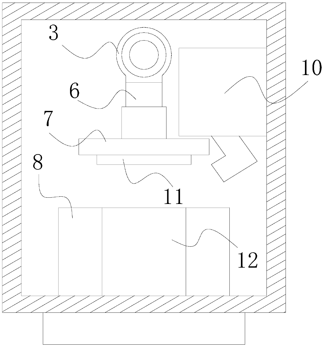
[0041] see Figure 1-6 , the present invention provides a technical solution for sheet-shaped inductance soldering equipment: its structure includes a high-efficiency energy-saving motor 1, a body 2, a mounting sleeve 3, a finished product placement cylinder 4, a screw rod 5, a hydraulic cylinder 6, a cooling device 7, a tin furnace 8, Nut pair 9, smog absorption and purification device 10, electromagnetic panel 11, and a tube 12 for placing parts to be soldered. A tin furnace 8 is fixed in the center of the inner bottom surface of the body 2. One side of the tin furnace 8 is provided with a finished product placement tube 4. One side is provided with a tube 12 for placing the parts to be soldered, and the tube 4 for placing the finished product and the tube 12 for placing the parts to be soldered are all connected to the inner wall of the body 2, and the tube 4 for the finished product can place the chip inductor that has been soldered. The setting of the solder part placemen...

Embodiment 3

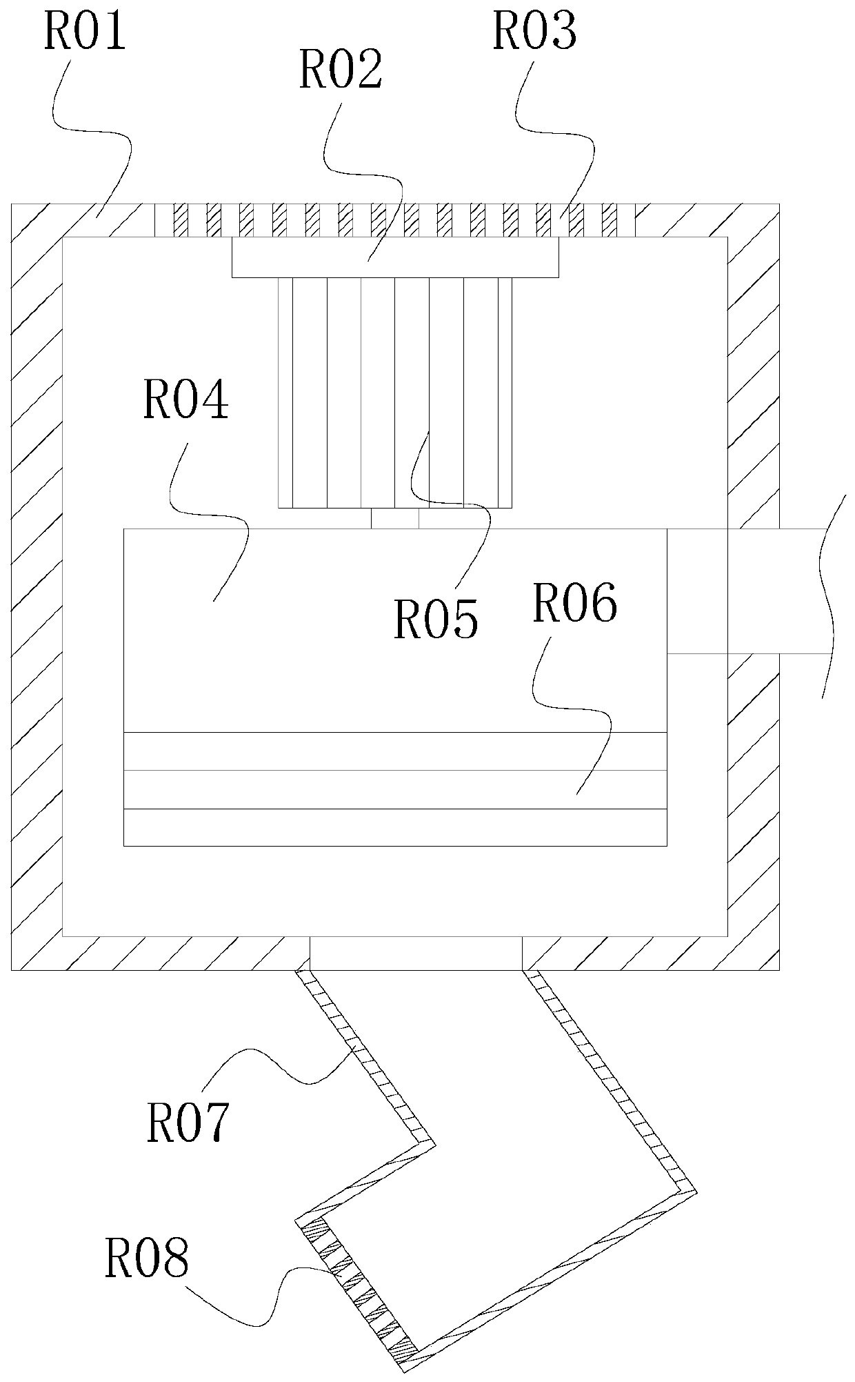
[0047] see Figure 1-8 , the present invention provides a technical solution for sheet-shaped inductance soldering equipment: its structure includes a high-efficiency energy-saving motor 1, a body 2, a mounting sleeve 3, a finished product placement cylinder 4, a screw rod 5, a hydraulic cylinder 6, a cooling device 7, a tin furnace 8, Nut pair 9, smog absorption and purification device 10, electromagnetic panel 11, and a tube 12 for placing parts to be soldered. A tin furnace 8 is fixed in the center of the inner bottom surface of the body 2. One side of the tin furnace 8 is provided with a finished product placement tube 4. One side is provided with a tube 12 for placing the parts to be soldered, and the tube 4 for placing the finished product and the tube 12 for placing the parts to be soldered are all connected to the inner wall of the body 2, and the tube 4 for the finished product can place the chip inductor that has been soldered. The setting of the solder part placemen...


PUM


Abstract

The invention discloses flaky inductance tin soldering equipment which structurally comprises an efficient energy-saving motor, a machine body, a mounting sleeve, a finished product placing cylinder,a screw rod, a hydraulic cylinder, a cooling device, a solder pot, a nut pair, a smog absorbing and purifying device, an electromagnetic panel, and a to-be-welded tin piece placing cylinder, wherein the solder pot is fixed in the center of the internal bottom surface of the machine body. Compared with the prior art, the flaky inductance tin soldering equipment has the following benefits: two conveyor belts capable of driving in opposite directions are utilized, and separating pieces are arranged on the conveyor belts, so that a plurality of to-be-welded tin flaky inductance placing grids are formed between the two conveyor belts; to-be-welded tin flaky inductance can be separately placed and conveyed one by one; the electromagnetic panel can attract one to-be-welded tin piece each time andcan absorb and carry out purified treatment on the smog generated during the tin soldering operation, so that the situation that an operator absorbs toxic gas during operation to thread the body health is prevented, improvement of the operating safety is facilitated and the operating environment is improved; and the cooling device is arranged to fast cool the flaky inductance after tin soldering.

Description

technical field [0001] The invention relates to the technical field of chip inductors, in particular to a chip inductor soldering equipment. Background technique [0002] Inductance is an electromagnetic induction element wound with insulated wires. Its main function is to isolate and filter AC signals or form a resonant circuit with capacitors and resistors. Soldering equipment is one of the important devices in the production process of inductance. Now Some soldering equipment has the following defects to be improved due to insufficient technology: [0003] 1) By electromagnetically absorbing the sheet inductance to be soldered, because the magnetic force can be attracted by objects, it will cause too much absorption of the sheet inductance to be soldered, which is not conducive to the progress of soldering; [0004] 2) During the soldering process, smoke will be produced, and the smoke contains slightly toxic gas. If the operator inhales the smoke, it will cause failure ...

Claims


Application Information

Patent Timeline
Patent Type & Authority Applications(China)
IPC IPC(8): B23K3/00B23K3/08B01D53/86B01D46/12
CPCB01D46/12B01D53/86B23K3/00B23K3/08B23K3/085
Inventor 张永成
Owner 张永成
Why Eureka
Try Eureka