Unmanned vehicle
An unmanned vehicle and frame technology, applied in the field of unmanned vehicles, can solve the problems of inability to realize center steering, low steering efficiency, and large steering radius, and achieve the effects of high steering efficiency, stable stability, and small steering radius
- Summary
- Abstract
- Description
- Claims
- Application Information
AI Technical Summary
Problems solved by technology
Method used
Image

Examples
Embodiment 1
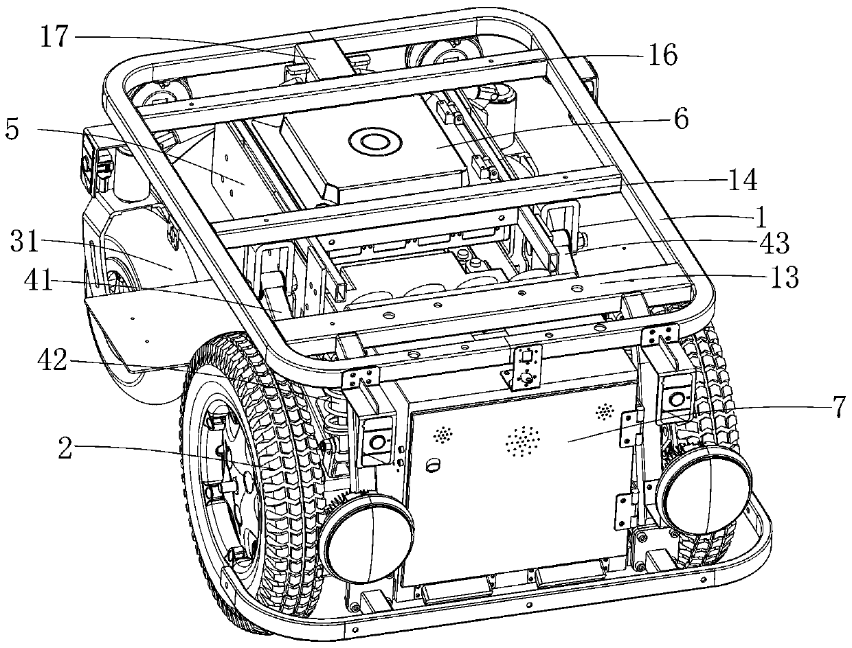
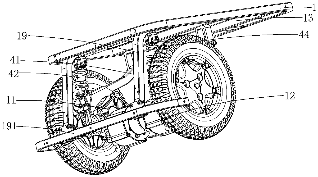
[0021] Such as Figure 1-4 As shown, a kind of unmanned vehicle comprises vehicle frame 1, and described vehicle frame 1 front portion is provided with two drive wheels 2, and described two drive wheels 2 are driven by respectively independent left drive motor 11 and right drive motor 12 Drive, the vehicle frame 1 rear portion is provided with at least one driven wheel 31, and described driven wheel 31 is universal wheel, through the setting of above-mentioned two drive motors and drive wheel, make above-mentioned each drive wheel all can realize self-rotation, And the speed of a driving wheel can be adjusted according to the steering angle, so that the steering of the unmanned vehicle can be realized through the difference in speed. At the midpoint, the in-situ steering can effectively improve the steering quality, and the setting of the driving wheel can increase the driving force of the unmanned vehicle, increase the output force, and improve the steering efficiency while i...
Embodiment 2
[0029] The difference between this embodiment and Embodiment 1 is:
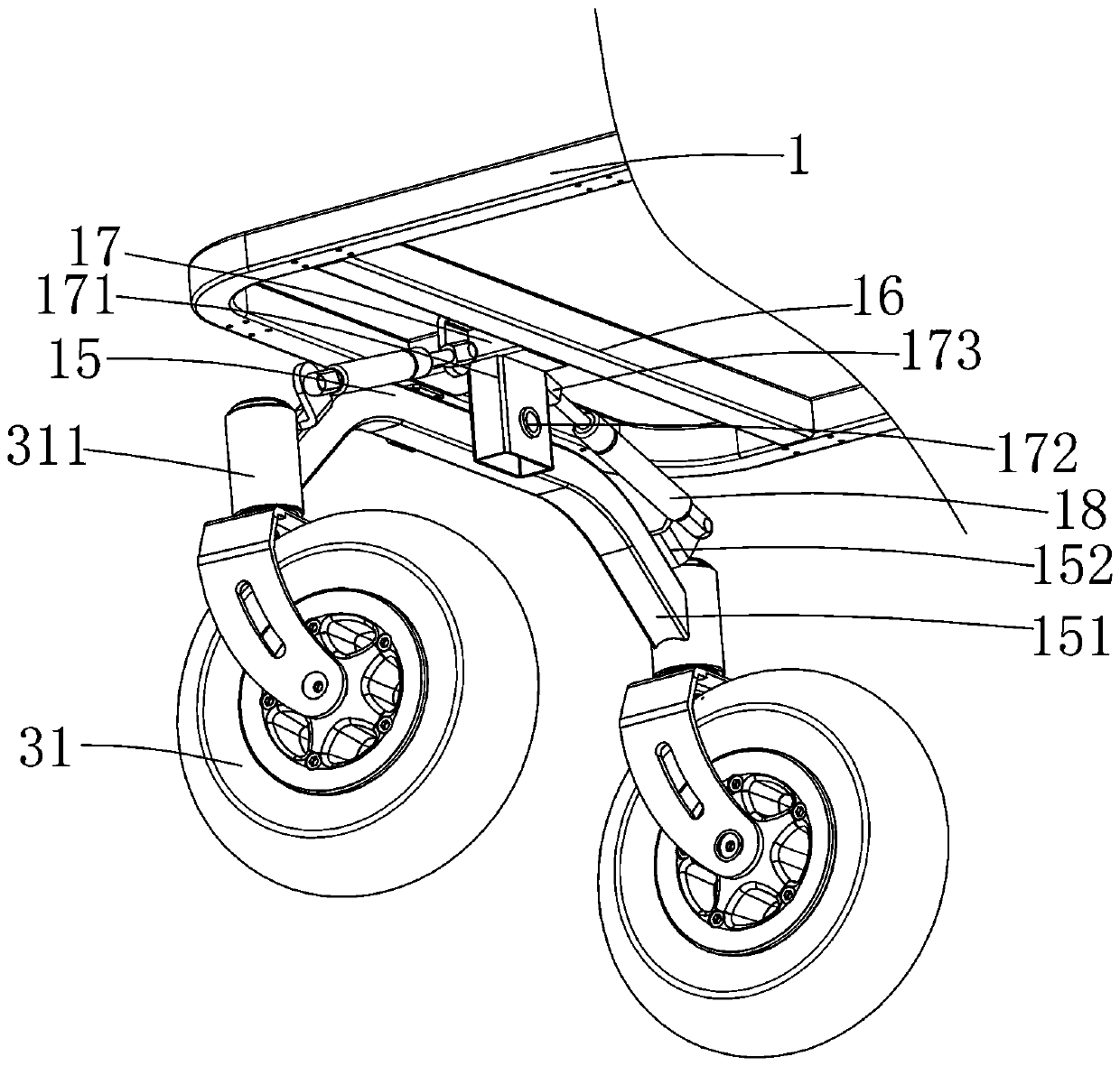
[0030] Such as Figure 4 As shown, a vertically arranged mechanical spring shock absorber 17 is respectively provided between the two ends of the rear swing arm 15 and the vehicle frame 1, and the vehicle frame 1 is provided with a connecting bar 18 extending downward. The rear swing arm 15 is connected to the connecting rod 18 through a pivot 181 to realize the rotational connection between the middle part of the rear swing arm 15 and the vehicle frame 1. The third beam 16 is provided with an upper ear body 161, and the rear swing arm 15 is provided with a lower ear body 151 on the side, and the upper and lower ends of the mechanical spring shock absorber 17 are hinged with the upper ear body 161 and the lower ear body 151 respectively. The left and right flips can be realized on the connecting bar, so as to realize the ups and downs adaptation to the wheels, and carry out stable and effective shock absorpt...
PUM
 Abstract
Description
Claims
Application Information
 - R&D
- Intellectual Property
- Life Sciences
- Materials
- Tech Scout
- Unparalleled Data Quality
- Higher Quality Content
- 60% Fewer Hallucinations
Browse by: Latest US Patents, China's latest patents, Technical Efficacy Thesaurus, Application Domain, Technology Topic, Popular Technical Reports.
© 2025 PatSnap. All rights reserved.Legal|Privacy policy|Modern Slavery Act Transparency Statement|Sitemap|About US| Contact US: help@patsnap.com