A high-precision desktop rotary ultrasonic rock coring device

A technology of rotating ultrasonic and coring devices, which is applied in the direction of extracting undisturbed core devices, drilling with vibration, earth square drilling and mining, etc. It can solve the problems of slow coring efficiency, easy to skew, rough surface, etc., and achieve the effect of improving coring efficiency

Active Publication Date: 2020-12-01
丁建利
View PDF5 Cites 0 Cited by
  • Summary
  • Abstract
  • Description
  • Claims
  • Application Information

AI Technical Summary

Problems solved by technology

[0002] Geological researchers can understand the history of the region through rock coring. Coring is done through a coring barrel. The traditional coring barrel is connected to the bottom end of the drill pipe close to the drill bit. After the core cutting head cuts into the formation, the coring barrel can be used Continuous coring, and then take it out from the drill pipe, most places use the wireline coring barrel, because in the process of coring, there is no need to take the drill pipe out of the well to take the core, and then continue to take the core, on the contrary, only need to take the core The core barrel is put into the drill pipe, automatically locked in the coring position, reaches the bottom of the well, and performs continuous coring. However, the coring efficiency of the existing coring device is slow, and each time the coring needs to be repeatedly extracted from the inner coring barrel for rock The sample is taken out, and the surface of the rock sample taken out by the existing device is rough, because the drill bit is easy to skew, which makes the quality of the core poor, which is not conducive to the observation and research of relevant personnel, so people need a high-precision desktop rotary ultrasonic rock coring device. solve the above problems

Method used


Image

  • A high-precision desktop rotary ultrasonic rock coring device
  • A high-precision desktop rotary ultrasonic rock coring device
  • A high-precision desktop rotary ultrasonic rock coring device

Examples


Embodiment

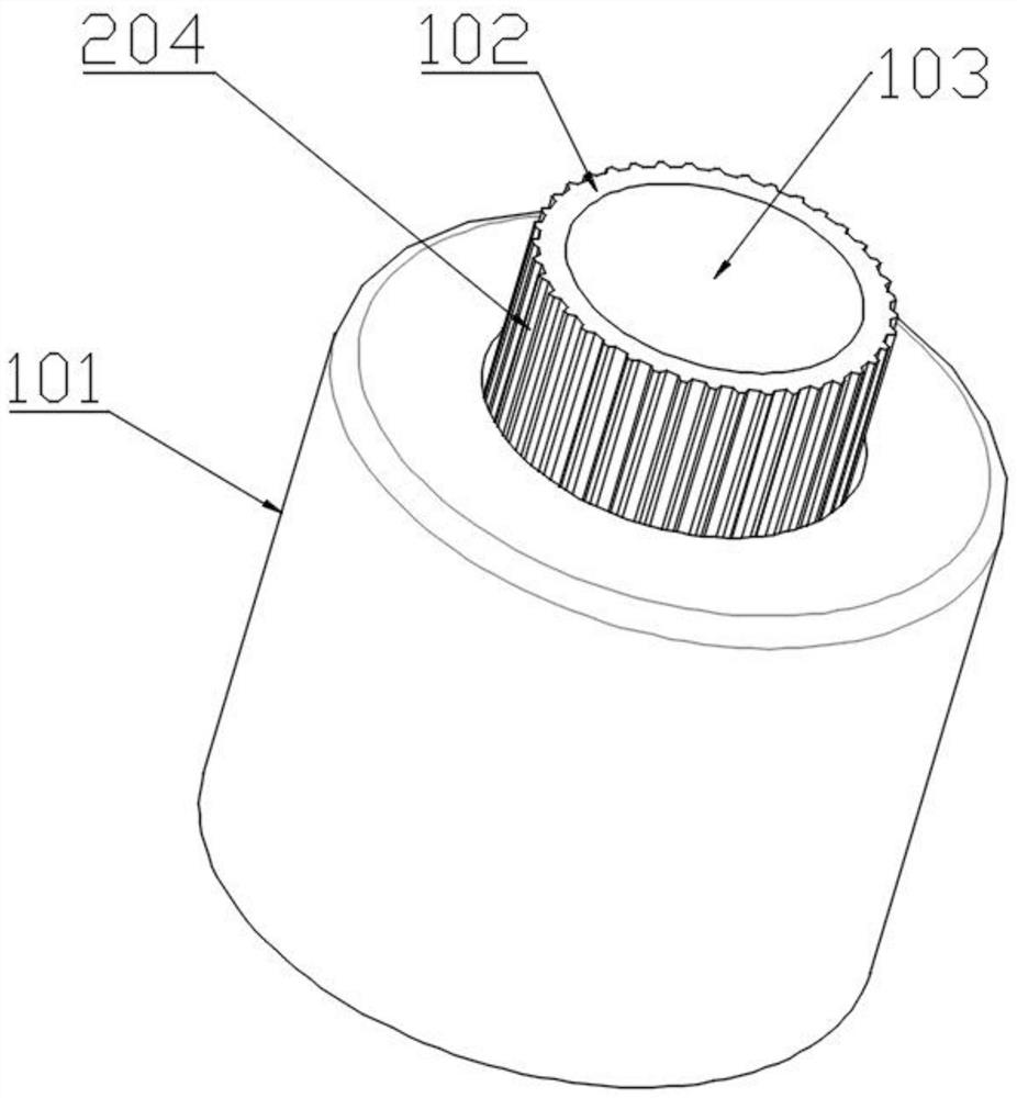
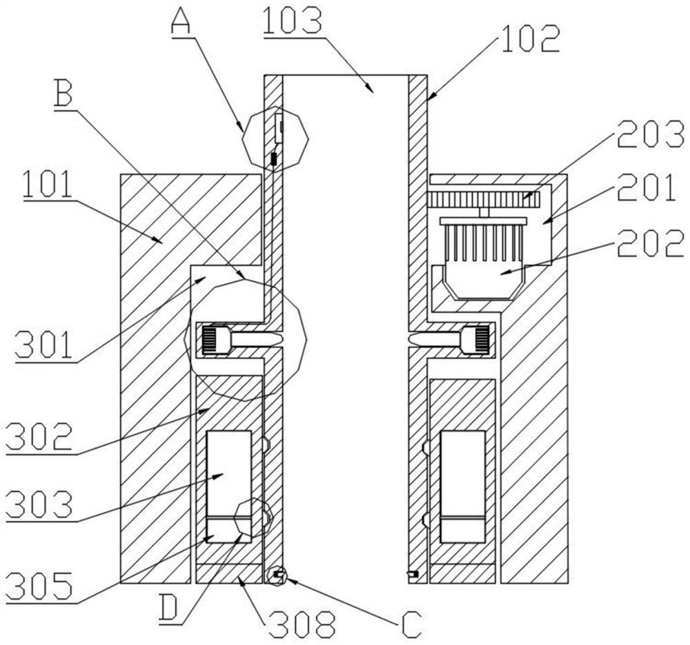
[0022] Example: such as Figure 1~6 As shown, a high-precision desktop rotary ultrasonic rock coring device includes a support assembly, a transmission assembly, an ultrasonic lithotripsy assembly, a cutting assembly, and a core lifting assembly. The role of components, the upper end of the support assembly is equipped with a transmission assembly, the transmission assembly is the power source for the operation of the device, the lower end of the support assembly is equipped with an ultrasonic lithotripsy assembly, the ultrasonic lithotripsy assembly plays the role of breaking rocks, and the middle of the support assembly is set There is a cut-off assembly, the cut-off assembly plays the role of cutting and segmenting the rock sample, the bottom of the support assembly is provided with a coring lifting assembly, and the coring lifting assembly plays the role of snapping in and supporting the rock coring sample.

[0023] The support assembly includes a counterweight housing 101...


PUM


Abstract

The invention discloses a high-precision table type rotating ultrasonic rock coring device, and belongs to the technical field of rock coring. The device comprises a supporting assembly, a transmission assembly and an ultrasonic rock breaking assembly. The supporting assembly is located on the outmost side of the whole device, the transmission assembly is located on the upper end in the supportingassembly, the ultrasonic rock breaking assembly is mounted on the lower end in the supporting assembly, the device is scientific and reasonable, use is safe and convenient, ultrasonic vibration is used for carrying out resonance breaking on the rock, compared with a traditional manner that a drill bit drills for coring, the coring efficiency is greatly improved, a rock sample can be subjected tosurface grinding through the device, the surface of a coring sample is flat, the rock sample can enter a coring groove favorably, a related worker can carry out observing and research, when the top end of the coring rock sample reaches the height of a distance sensor, the device can cut off the rock sample, the cut-off rock coring sample can be conveniently taken out by an operator from the top ofa coring groove, and convenience and rapidness are achieved.

Description

technical field [0001] The invention relates to the technical field of rock coring, in particular to a high-precision desktop rotary ultrasonic rock coring device. Background technique [0002] Geological researchers can understand the history of the region through rock coring. Coring is done through a coring barrel. The traditional coring barrel is connected to the bottom end of the drill pipe close to the drill bit. After the core cutting head cuts into the formation, the coring barrel can be used Continuous coring, and then take it out from the drill pipe, most places use the wireline coring barrel, because in the process of coring, there is no need to take the drill pipe out of the well to take the core, and then continue to take the core, on the contrary, only need to take the core The core barrel is put into the drill pipe, automatically locked in the coring position, reaches the bottom of the well, and performs continuous coring. However, the coring efficiency of the ...

Claims


Application Information

Patent Timeline
Patent Type & Authority Patents(China)
IPC IPC(8): E21B25/00E21B25/10E21B7/24
CPCE21B7/24E21B25/00E21B25/10
Inventor 于鹏飞
Owner 丁建利
Why Eureka
Try Eureka