Non-contact vibration measuring device for aero-engine blade

An aero-engine, non-contact technology, applied in the field of measurement, can solve the problems of poor sensor anti-interference ability, long preparation time, limited real-time, high precision, etc., to achieve the effect of convenient monitoring at any time, simple and convenient measurement, and protection of the internal structure

Pending Publication Date: 2020-06-23
北京融智世纪节能技术服务有限公司
View PDF5 Cites 0 Cited by
  • Summary
  • Abstract
  • Description
  • Claims
  • Application Information

AI Technical Summary

Problems solved by technology

This method has high precision, but it is a lot of work to paste the strain gauges on many rotor blades. When the engine is tested, it needs to be specially installed and disassembled, the wiring is complicated, the pre-test preparation time is long, and the reliability is poor. The rotational speed and working temperature of aero-engines are getting higher and higher, and the centrifugal force and temperature borne by the resistance strain gauges pasted on the blades are becoming more and more severe during the working process, which makes the pasted strain gauges unable to work for a long time, and generally can only last for 10 -30 minutes
Moreover, the load and volume of the strain gauge installed on the blade will seriously affect the aerodynamic efficiency of the blade, thus limiting the application of this technology in real-time, high precision and high speed.
[0005] Other aeroengine rotor blade measurement methods include laser Doppler method, electromagnetic method, intermittent phase method, blade tip timing measurement method, blade tip clearance measurement method, and dynamic pressure measurement method between blades. These methods are either in the engine Opening holes on the surface of the casing, or installing sensors on the blades, both have complex system structures, long preparation time, expensive detection methods, poor anti-interference ability of sensors, and online detection and monitoring of blade vibration when the engine is running cannot be realized.
At present, it has not been widely used in the field of engineering

Method used


Image

  • Non-contact vibration measuring device for aero-engine blade
  • Non-contact vibration measuring device for aero-engine blade
  • Non-contact vibration measuring device for aero-engine blade

Examples


Embodiment Construction

[0035] The specific embodiments of the present invention will be further described below in conjunction with the accompanying drawings. It should be noted here that the descriptions of these embodiments are used to help understand the present invention, but are not intended to limit the present invention. In addition, the technical features involved in the various embodiments of the present invention described below may be combined with each other as long as they do not constitute a conflict with each other.

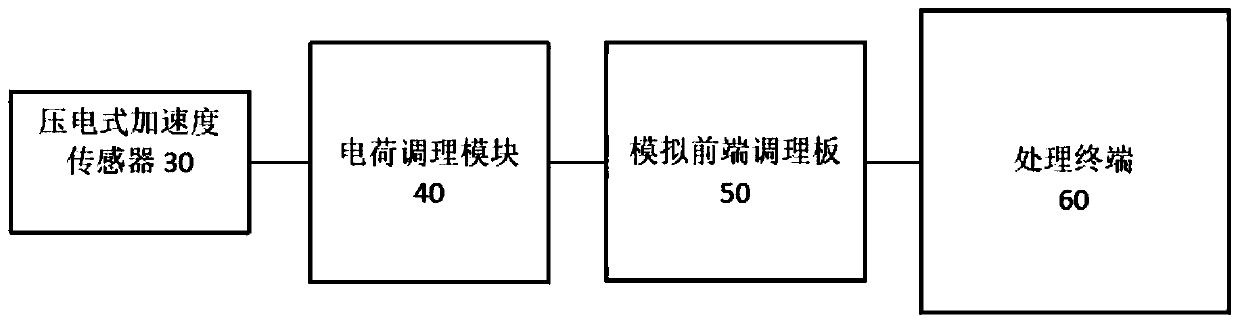
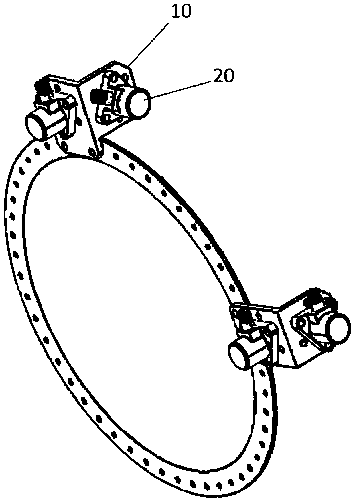
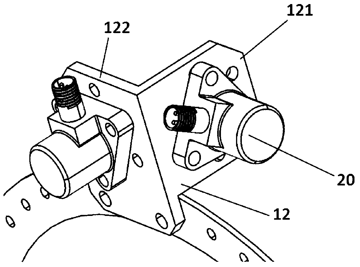
[0036] A non-contact vibration measurement device for an aeroengine blade, such as figure 1 machine figure 2 As shown, it includes a mounting bracket 10, several piezoelectric acceleration sensors 20, a charge conditioning module 30, an analog front-end conditioning board 40, and a processing terminal 50;

[0037] The mounting bracket 10 is arranged on the flange side of the aero-engine casing, the piezoelectric acceleration sensor 20 is fixed on the mounting bracket ...


PUM


Abstract

The invention relates to the field of measurement, and particularly provides a non-contact vibration measurement device for an aero-engine blade, which comprises a sensor mounting bracket, a pluralityof piezoelectric acceleration sensors, a charge conditioning module, an analog front-end conditioning board and a processing terminal. According to the invention, the structure is adopted, by arranging the piezoelectric acceleration sensor on the aero-engine shell, online detection and monitoring of the blade are achieved, the device has the advantages of being simple and convenient to measure, free of any influence on the measured blade and the engine structure, free of influence of the rotating speed, the operating temperature and the time of the engine and easy to disassemble and assemble,and convenience is brought to testers in use.

Description

technical field [0001] The invention relates to the measurement field, in particular to a non-contact vibration measurement device for an aeroengine blade. Background technique [0002] The main rotating parts of an aero-engine are blades, discs, gears, shafts, bearings, etc. Among them, blades are important parts of aero-engines. Due to the large number of blades, complex geometric shapes, and extremely harsh working conditions, the installation of blades has always been a The design and manufacturing technology of aero-engines is a difficult point, and the blades are also the most prone to serious failures during the use of the engine. According to statistics, more than 70% of modern aero-engine engine failures are caused by blade damage. At the same time, in order to ensure the safe operation of the engine, the blade must avoid the resonance area of ​​each blade during design to avoid the occurrence of blade resonance. [0003] For this reason, in the prior art, in addit...

Claims


Application Information

Patent Timeline
IPC IPC(8): G01M7/02
CPCG01M7/025G01M7/027
Inventor 陈阳
Owner 北京融智世纪节能技术服务有限公司
Why Eureka
Try Eureka