Unlock instant, AI-driven research and patent intelligence for your innovation.

Method for simulating cutting using dynamic position error

A technology of dynamic position and cutting method, which is applied in general control systems, special data processing applications, instruments, etc., can solve problems such as long calculation time and inability to respond to die surface defects, and achieve easy observation, improved simulation speed, and estimated position accurate effect

Pending Publication Date: 2020-06-23
IND TECH RES INST
View PDF4 Cites 0 Cited by
  • Summary
  • Abstract
  • Description
  • Claims
  • Application Information

AI Technical Summary

Problems solved by technology

[0003] It can be seen from the above that CAD and CAM software only use machining program codes to roughly simulate machining and cutting results. In other words, the existing technology is to input the machining program codes into the machine tool and perform volume elimination according to the machining path of the machining program codes. As the cutting simulation result, it can only simulate whether the tool interferes with the machine tool, or simulate the height of the residual material on the cutting die surface, and does not include the simulation results of dynamic errors caused by control, interpolation, and machine tool structure.
Therefore, the cutting simulation method using CAD and CAM software in the prior art cannot reflect the real situation that dynamic errors cause defects on the die surface, and the calculation of volume elimination will make the calculation time too long

Method used


Image

  • Method for simulating cutting using dynamic position error
  • Method for simulating cutting using dynamic position error
  • Method for simulating cutting using dynamic position error

Examples


Embodiment Construction

[0033] The specific implementation manners of the present invention will be further described below in conjunction with the accompanying drawings and examples. The following examples are only used to illustrate the technical solutions of the present invention more clearly, but not to limit the protection scope of the present invention. It should be noted that, for the convenience and clarity of description, the thickness or size of each element in the drawings is exaggerated, omitted or approximated, and the size of each element is not entirely its actual size.

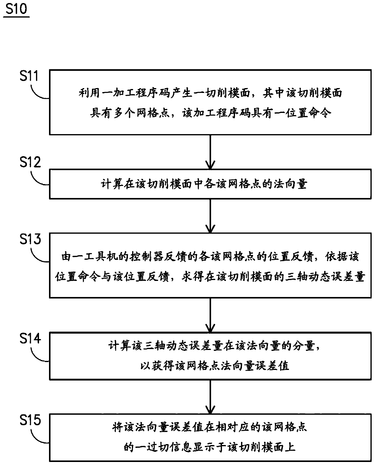
[0034] figure 1 It is a flow chart of an embodiment of the method for simulating cutting by using dynamic position error of the present invention. see figure 1 The cutting method S10 using dynamic position error simulation in this embodiment can be implemented through hardware (such as a processor, computer, host computer), software (such as program instructions executed by a processor) or a combination thereof. In ...


PUM


Abstract

A method for simulating cutting using dynamic position error, suitable for connecting to a controller of a machine tool, including the following steps: generating a cutting die surface using a machining program code; calculating the normal vector of each grid point in the cutting die surface; according to various position commands and corresponding position feedback, obtaining the three-axis dynamic error on the cutting die surface; calculating the component of the normal vector of the three-axis dynamic error on the cutting die surface to obtain the normal vector error value of each grid point; and displaying the overcut information of the normal vector error value at the corresponding grid point on the cutting die surface.

Description

technical field [0001] The invention relates to a simulated cutting method, in particular to a simulated cutting method utilizing dynamic position error. Background technique [0002] When simulating machining and cutting, in order to predict the impact of errors on the die surface, the existing technology usually uses CAD and CAM software, such as NX, CATIA, VERICUT, etc. Generally, in the method of simulating machining and cutting using CAD and CAM software, the machining program code input to the machine tool is used to let the tool follow the machining path of the machining program code to eliminate the intersection volume of the workpiece and the tool to remove material to achieve simulation. The purpose of machining and cutting. [0003] It can be seen from the above that CAD and CAM software only use machining program codes to roughly simulate machining and cutting results. In other words, the existing technology is to input the machining program codes into the machi...

Claims


Application Information

Patent Timeline
IPC IPC(8): G06F30/23
CPCG05B19/4069G05B2219/35346G05B2219/45145G06F30/20Y02P90/02G05B19/4099G06F17/16G05B19/258
Inventor 王承纬周国华廖建智王仁杰
Owner IND TECH RES INST