
Permanent magnet motor emergency brake control method, system and device

An emergency braking, permanent magnet motor technology, applied in the control system, motor control, AC motor control and other directions, to achieve the effect of less components, simple circuit structure and effective protection

Active Publication Date: 2020-06-23
BEIJING CTB SERVO CO LTD
View PDF4 Cites 5 Cited by
  • Summary
  • Abstract
  • Description
  • Claims
  • Application Information

AI Technical Summary

Problems solved by technology

[0003] The present invention aims to provide a permanent magnet motor emergency braking control method, system and device, at least partly solving the technical problem of how to realize the emergency braking of the permanent magnet synchronous motor through the servo system itself, so that when the CNC machine tool has a servo failure There is no need to increase the complexity of equipment, fast braking, and protection of workpieces and tools at the same time

Method used


Image

  • Permanent magnet motor emergency brake control method, system and device
  • Permanent magnet motor emergency brake control method, system and device
  • Permanent magnet motor emergency brake control method, system and device

Examples


Embodiment Construction

[0023] In order to facilitate the understanding of the invention, the present invention will be described more comprehensively and in detail below in conjunction with the accompanying drawings and embodiments, but those skilled in the art should understand that these embodiments are only used to explain the technical principles of the present invention, and are not intended to Limit the protection scope of the present invention.

[0024] It should be noted that, in the description of the present invention, the terms "upper", "lower", "left", "right" and other terms indicating direction or positional relationship are based on the direction or positional relationship shown in the drawings, which are only It is for the convenience of description, and does not indicate or imply that the device or element must have a specific orientation, be constructed and operate in a specific orientation, and thus should not be construed as limiting the present invention. In addition, the terms ...


PUM


Abstract

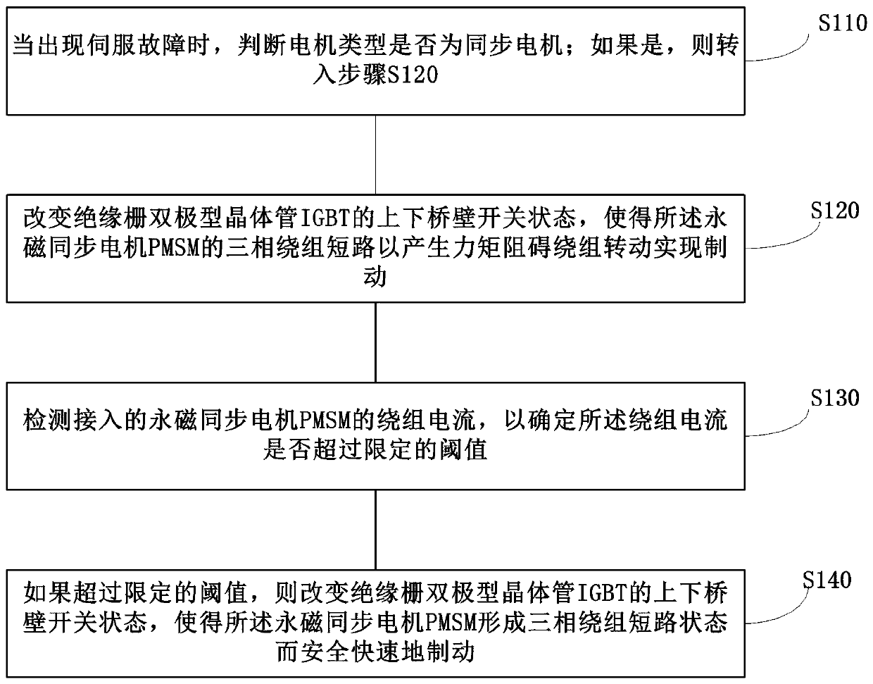
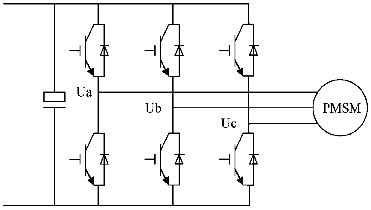
The invention discloses a permanent magnet motor emergency brake control method, system and device. The method comprises that: when a servo fault occurs, the on-off state of the upper bridge wall andthe lower bridge wall of an insulated gate bipolar transistor IGBT is changed, so that a three-phase winding of the PMSM is short-circuited to generate torque to hinder rotation of the winding to achieve braking; the winding current of the accessed PMSM is detected so as to determine whether the winding current exceeds a limited threshold value or not; and the on-off states of the upper bridge wall and the lower bridge wall of the insulated gate bipolar transistor IGBT are changed if the voltage exceeds the limited threshold value, so that the PMSM forms a three-phase winding short-circuit state to safely and quickly brake. Rapid braking of the synchronous motor is achieved through an existing servo structure, the circuit structure is simple, braking is safe and rapid, and reliability is high.

Description

technical field [0001] This specification belongs to the field of permanent magnet motor servo technology, and in particular relates to a permanent magnet motor emergency braking control method, system and device. Background technique [0002] In the prior art, when a CNC machine tool has a servo failure, the emergency braking of the motor is usually blocked by a counterweight unit and an external relay to complete the braking. Since the use of the relay takes a certain amount of time to lock, the speed is relatively slow, resulting in a certain amount of falling of the vertical axis on the CNC machine tool, resulting in the loss of workpieces and tools. The counterweight unit prevents the vertical axis from falling. Therefore, the locking or braking speed of the current motor is slow, and the addition of an additional counterweight unit leads to high equipment complexity and cost. Therefore, there is a need for a control scheme for emergency braking of permanent magnet mo...

Claims


Application Information

Patent Timeline
Patent Type & Authority Applications(China)
IPC IPC(8): H02P6/24H02P3/22H02P29/02H02P29/024H02P23/20H02P25/024H02P27/06
CPCH02P6/24H02P3/22H02P29/02H02P29/027H02P23/20H02P25/024H02P27/06H02P2207/05
Inventor 庞建军徐忠利华纯
Owner BEIJING CTB SERVO CO LTD
Learn More