
High-speed mixing equipment for metallurgical powder of engine rotating part

A technology of rotating parts and high-speed mixing, which is applied to mixer accessories, mixers, mixers with rotating stirring devices, etc. It can solve problems such as low work efficiency, poor uniformity, and impact on parts quality, and achieve good results. Effect

Active Publication Date: 2020-06-26
广东华于科技股份有限公司
View PDF5 Cites 2 Cited by
  • Summary
  • Abstract
  • Description
  • Claims
  • Application Information

AI Technical Summary

Problems solved by technology

[0004] The purpose of the present invention is to provide a high-speed mixing equipment for the metallurgical powder of the rotating parts of the engine, which can solve the problem that the existing mixing equipment has a simple structure, but simply mixes various raw materials, and the mixing is not sufficient and uniform, and Multiple processes are required, the equipment takes up a lot of space, and the work efficiency is low
The impact of different diameters and weights of various raw material particles on mixing cannot be resolved, resulting in poor uniformity after mixing, and technical problems that affect the quality of subsequent processed parts to a certain extent

Method used


Image

  • High-speed mixing equipment for metallurgical powder of engine rotating part
  • High-speed mixing equipment for metallurgical powder of engine rotating part
  • High-speed mixing equipment for metallurgical powder of engine rotating part

Examples


Embodiment Construction

[0042] The technical solutions of the present invention will be clearly and completely described below in conjunction with the embodiments. Apparently, the described embodiments are only some of the embodiments of the present invention, not all of them. Based on the embodiments of the present invention, all other embodiments obtained by persons of ordinary skill in the art without creative efforts fall within the protection scope of the present invention.

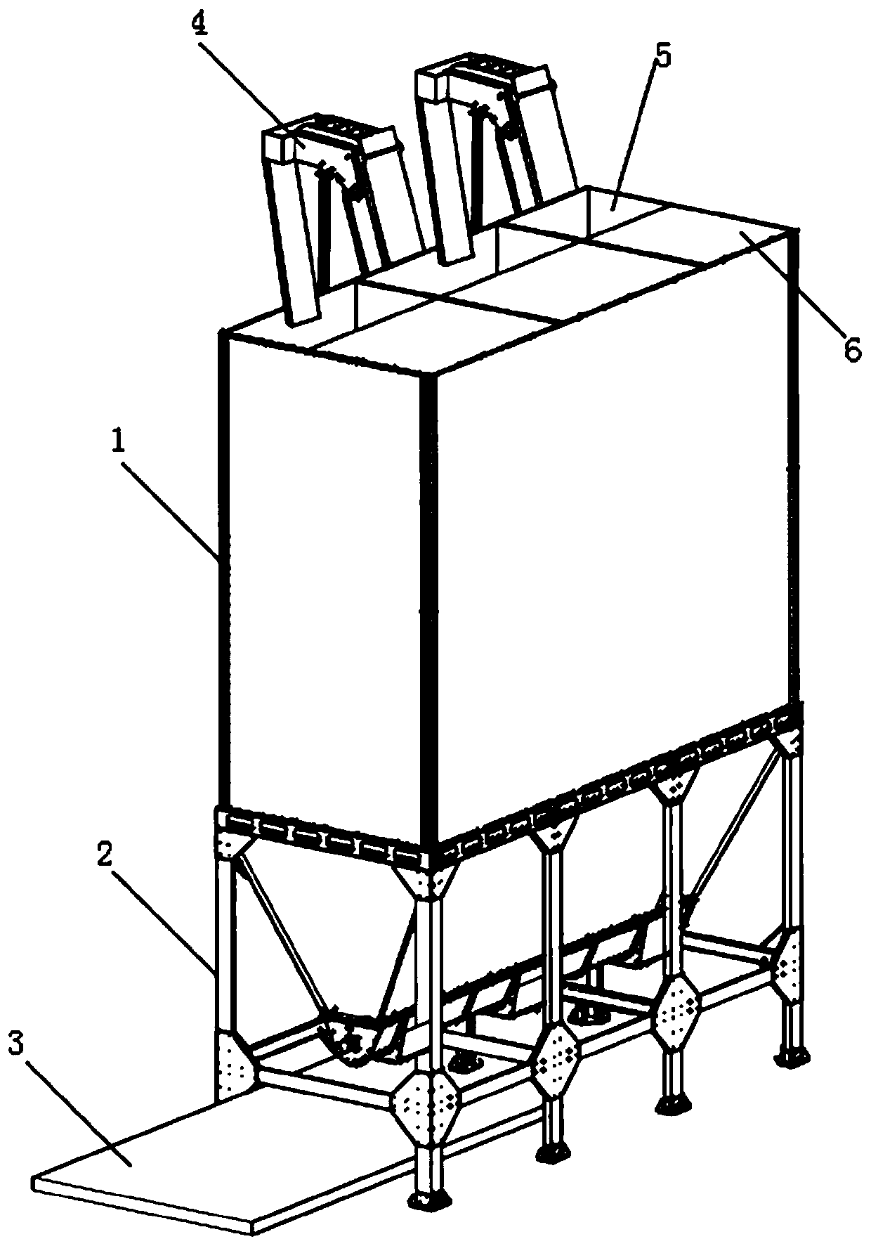
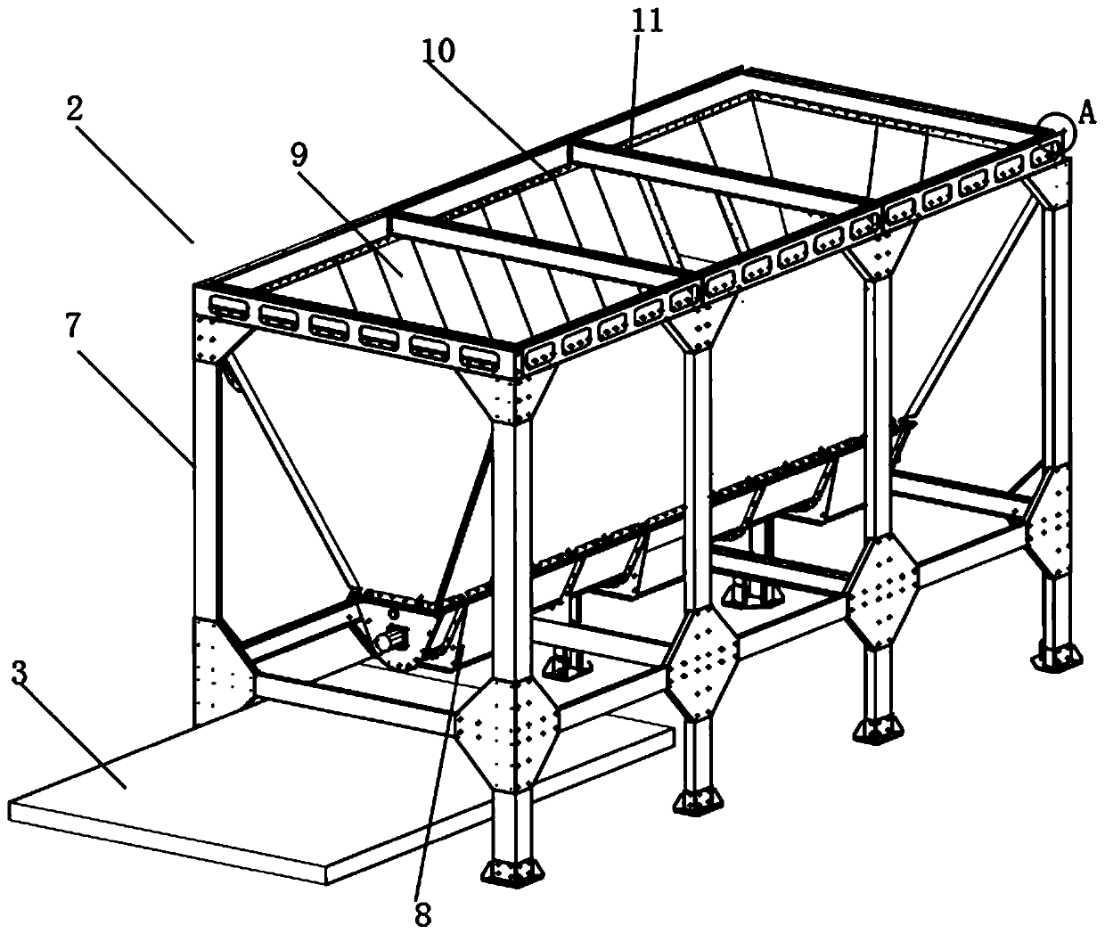
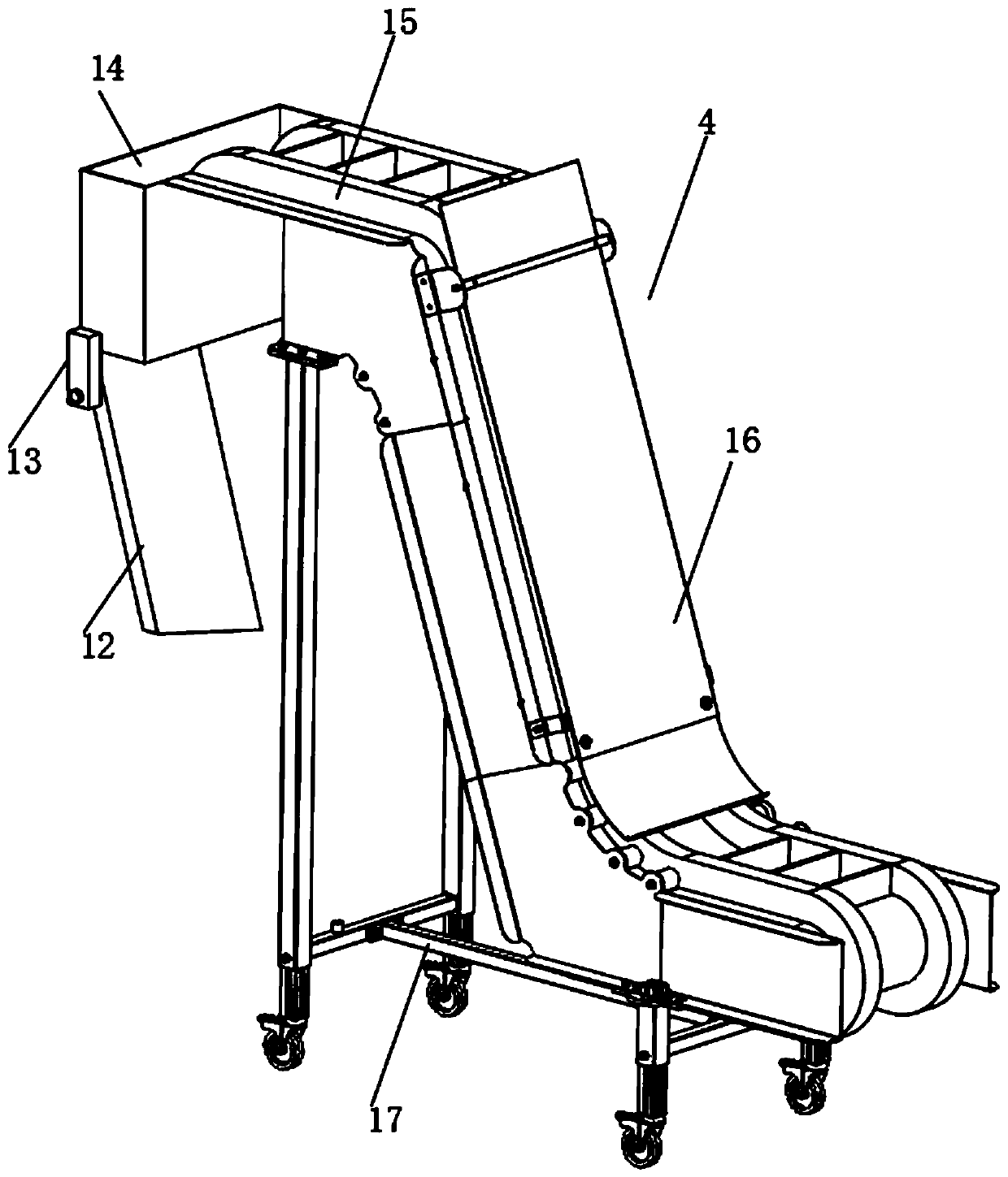
[0043] see Figure 1-11 As shown, a high-speed mixing equipment for metallurgical powder of engine rotating parts includes a mixing box 1 and a discharge mechanism 2. The discharge mechanism 2 is installed under the mixing box 1. There are three sets of loading equipment inside the mixing box 1. The inside of each loading chamber is equipped with several mixing chambers 27 from top to bottom, and a mixing mechanism is installed inside each mixing chamber 27. A fourth rotating shaft 31 is installed on the top of the mixing c...


PUM


Abstract

The invention discloses high-speed mixing equipment for metallurgical powder of an engine rotating part. The equipment comprises a mixing box and a discharging mechanism, the discharging mechanism ismounted below the mixing box, three groups of loading cavities are formed in the mixing box, a plurality of mixing cavities are formed in each loading cavity from top to bottom, a mixing mechanism isinstalled in each mixing cavity, a fourth rotating shaft is rotatably installed on the upper part in each mixing cavity, a plurality of second mixing rods and a plurality of third rotating shafts areinstalled outside the fourth rotating shafts, the third rotating shafts are rotatably installed outside the second mixing rods, and a plurality of cutting knives are connected to the exteriors of thethird rotating shafts in a staggered mode; second rotating shafts drives a plurality of external crushing cutters to cut falling raw materials, and the extruded raw materials are cut and crushed, so that one particle contains a variety of different raw materials, and the variety of raw materials are mixed more uniformly. And the influence of inconsistent particle sizes and inconsistent weights ofthe various raw materials on mixing is reduced.

Description

technical field [0001] The invention relates to a material mixing device, in particular to a high-speed material mixing device for metallurgical powder of engine rotating parts, belonging to the application field of engine parts processing. Background technique [0002] The car engine is the machine that provides power for the car, and it is the heart of the car, which affects the power, economy and environmental protection of the car. According to different power sources, automotive engines can be divided into diesel engines, gasoline engines, electric vehicle motors, and hybrids. The engine contains a large number of rotating parts, and the rotating parts are often processed by various materials. In order to improve the processing quality, the raw materials are fully mixed by mixing equipment before processing. [0003] But there are certain deficiencies in existing mixing equipment in use. The existing mixing equipment has a simple structure, and only simply mixes and s...

Claims


Application Information

Patent Timeline
Patent Type & Authority Applications(China)
IPC IPC(8): B01F7/04B01F13/10B01F15/02
CPCB01F27/625B01F27/70B01F33/8305B01F33/811B01F33/831B01F33/83611B01F33/83612B01F35/71705B01F35/7541
Inventor 蔡立华
Owner 广东华于科技股份有限公司
Learn More