Separate system controlling sewage and initial rainwater pollution

A technology of initial rainwater and diversion system, which is applied in waterway systems, sewer systems, water supply devices, etc., and can solve problems such as mixed connection of pipelines, inability to sewage, precise control of initial rainwater, and pollution of natural water bodies

Pending Publication Date: 2020-06-26
NANJING INST OF ENVIRONMENTAL SCI MINIST OF ECOLOGY & ENVIRONMENT OF THE PEOPLES REPUBLIC OF CHINA +1
View PDF11 Cites 5 Cited by
  • Summary
  • Abstract
  • Description
  • Claims
  • Application Information

AI Technical Summary

Problems solved by technology

[0004] For this combined drainage system, the main problems are: ① When it rains, non-point source pollution will be generated on residential areas and municipal roads. Although the existing combined drainage system has an interception well at the end for interception, the designed interception The multiple is not enough, so that the interception well fails to intercept the non-point source pollutants, and the non-point source pollutants directly enter the natural water body, causing pollution to the natural water body
② To control non-point source pollution, it is necessary to increase the size of the interception well, increase the size of the interception main pipe, and increase the capacity of the sewage plant
③ The interception of the interception well is controlled extensively, and the initial rainwater cannot be accurately intercepted
There are many problems in this split drainage system: ① Some sewage in the residential area enters the rainwater pipe by mistake, for example, the sewage discharged from the washing machine on the balcony will be directly discharged into the natural water body
The main problems of this drainage system are: ①The entire system cannot effectively intercept non-point source pollutants, and the interception efficiency is low
② Unable to control the sewage entering the rainwater pipe
④ Extensive control of interception wells. On the one hand, it may not be possible to send more initial rainwater to the sewage plant for treatment, causing non-point source pollutants to be discharged into natura

Method used


Image

  • Separate system controlling sewage and initial rainwater pollution
  • Separate system controlling sewage and initial rainwater pollution
  • Separate system controlling sewage and initial rainwater pollution

Examples


Example Embodiment

[0046] Example one

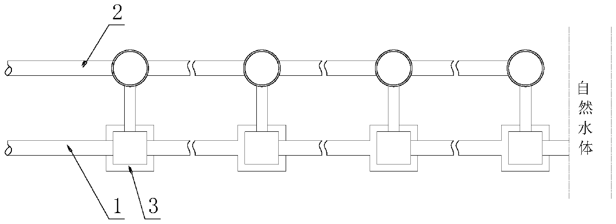
[0047] Such as Figure 1-4 As shown, a diversion system for controlling sewage and initial rainwater pollution includes a rainwater pipe 1, a sewage pipe 2 and a diversion control unit 3. The rainwater pipe 1 is parallel to the sewage pipe 2, and the rainwater pipe 1 is provided with several diversions. Control unit 3, the diversion control unit 3 is connected to the sewage pipe 2 through the diversion pipe;

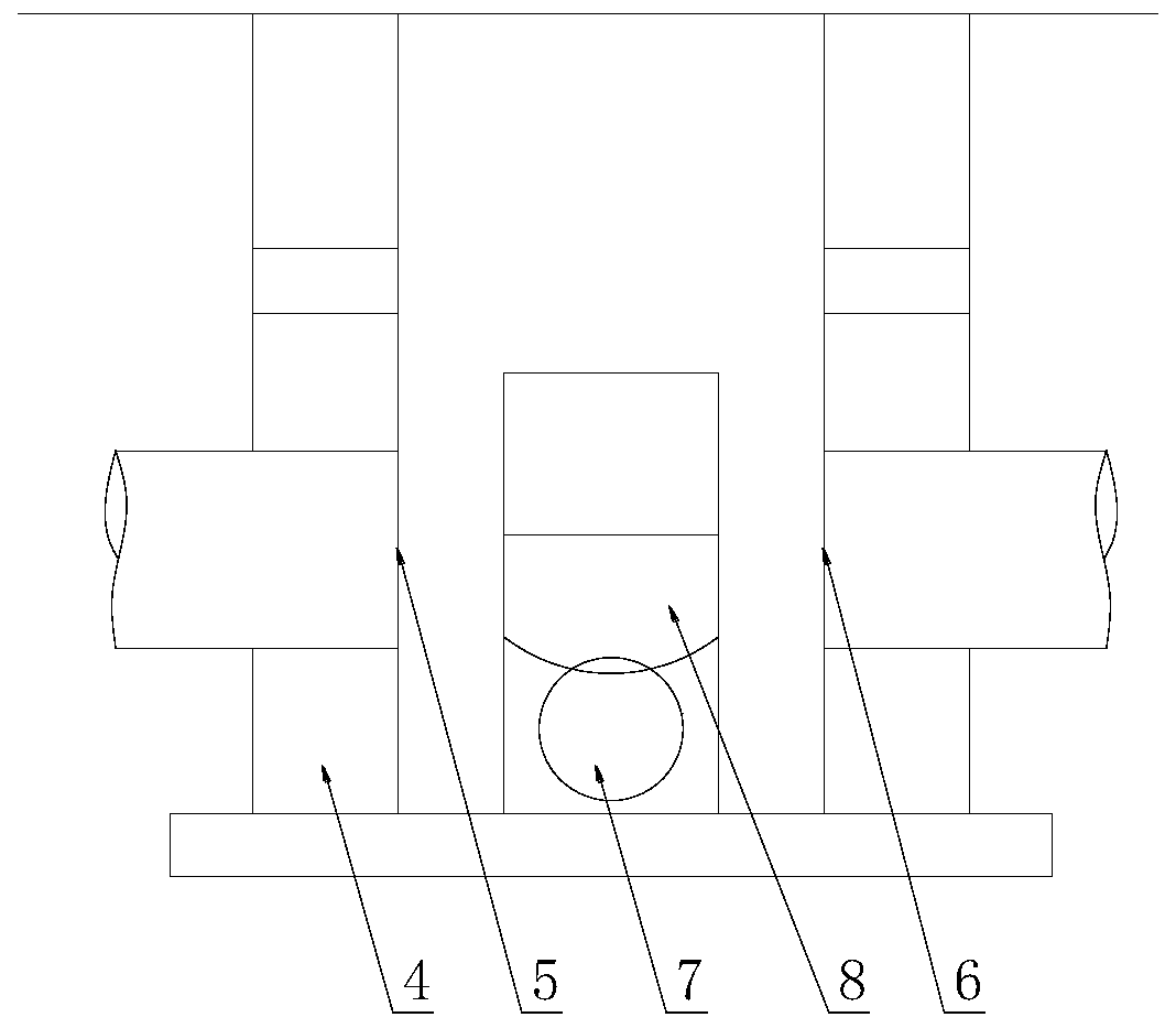
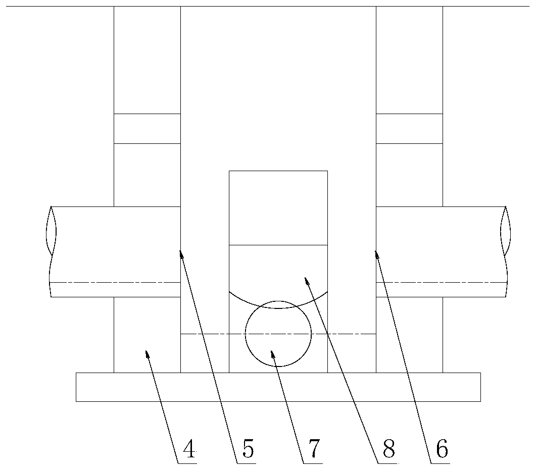
[0048] The diversion control unit 3 includes a diversion well 4, one side of the diversion well 4 is provided with a first inlet 5, the first inlet 5 corresponds to the other side of the diversion well 4 is provided with a first outlet 6, the first inlet 5 and the first outlet 6 Connect the rainwater pipe 1 on both sides of the shunt well 4 respectively;

[0049] The diversion well 4 is provided with a second outlet 7 on the side close to the sewage pipe 2, and the second outlet 7 is connected to the inlet end of the diversion pipe, and the outlet end of t...

Example Embodiment

[0058] Example two

[0059] Such as Figure 5 As shown, as a specific implementation, the passage control unit 8 includes a dynamic power transmission mechanism 81, a lifting mechanism 82, an opening and closing mechanism 83, and a resetting mechanism 84. The dynamic power transmission mechanism 81 is connected to the opening and closing mechanism through the lifting mechanism 82. 83. The opening and closing mechanism 83 is arranged on the second outlet 7 to control the opening of the second outlet 7; the reset mechanism 84 is connected to the lifting mechanism 82 to drive the opening and closing mechanism 83 to reset;

[0060] The dynamic power transmission mechanism 81 includes an impeller 811, an input shaft 812, a reversing transmission mechanism 813 and an output shaft 814;

[0061] The lifting mechanism 82 includes a gear 821 and a rack 822;

[0062] The opening and closing mechanism 83 includes a valve plate 831 and a sliding seat 832;

[0063] The reset mechanism 84 includes a ...

Example Embodiment

[0071] Example three

[0072] Such as Figure 6-7 As shown, and further, as an optimization of the second embodiment, the output shaft 814 is connected to a limit mechanism. The limit mechanism includes a ratchet wheel 851, a pawl 852, a spring 853, a slider 854, a sliding rail 855, a connecting rod 856 and a float 857, the ratchet wheel 851 is fixed on the output shaft 814, the ratchet wheel 851 is matched with the pawl 852, the pawl 852 is connected to the slider 854 through a pin, and a spring 853 is arranged between the bottom of the pawl 852 and the slider 854, the slider 854 is slidably connected to the sliding rail 855 in the diversion well 4, the bottom of the sliding block 854 is fixedly connected to the upper end of the connecting rod 856, and the lower end of the connecting rod 856 is fixedly connected to the floating ball 857.

[0073] The floating ball 857 is affected by the liquid level in the diversion well 4. When there is no liquid level or the liquid level is low...


PUM


Abstract

The invention relates to a separate system controlling sewage and initial rainwater pollution. The separate system controlling sewage and initial rainwater pollution comprises a rainwater pipeline, asewage pipeline and separating control units. The rainwater pipeline and the sewage pipeline are parallel. The rainwater pipeline is provided with a plurality of separating control units. Each separating control unit is connected with the sewage pipeline through a separating pipeline. Each separating control unit comprises a separating well, wherein one side of the separating well is provided witha first inlet, the other side of the separating well is provided with a first outlet corresponding to the first inlet, the first inlet and the first outlet are connected with rainwater pipeline sections on the two sides of the separating well correspondingly, and the side, close to the sewage pipeline, of the separating well is provided with a second outlet. Each separating control unit is provided with a passage control unit which is used for controlling the opening degree of the second outlet. The separate system controlling sewage and initial rainwater pollution creatively adopts a rainwater pipeline separating manner and avoids the situation that initial rainwater of rainfall, ground cleaning sewage and mixed discharge of sewage and rainwater pollute natural water.

Description

technical field [0001] The invention belongs to the technical field of environmental protection, and in particular relates to a diversion system for controlling sewage and initial rainwater pollution. Background technique [0002] Urban municipal drainage systems are mainly divided into combined drainage systems and divergent drainage systems. The earliest combined drainage system is to mix sewage, industrial wastewater and rainwater in the same pipe, and directly discharge it into the nearby water body without any treatment, which seriously pollutes the receiving water body. Many old cities at home and abroad are almost Take this approach. The interception combined drainage system is often used now. [0003] The structure of the intercepting combined drainage system is basically the same as that of the traditional combined drainage system. The difference is that the intercepting combined drainage system has an intercepting well between the municipal combined main pipe and...

Claims


Application Information

Patent Timeline
IPC IPC(8): E03F3/02E03F5/10E03F7/02
CPCE03F3/02E03F5/10E03F5/101E03F7/02E03F2201/10
Inventor 丁程成崔益斌戴建华王曙东
Owner NANJING INST OF ENVIRONMENTAL SCI MINIST OF ECOLOGY & ENVIRONMENT OF THE PEOPLES REPUBLIC OF CHINA
Why Eureka
Try Eureka