Arm rest and work equipment

A boom and frame structure technology, used in fire rescue, construction, cranes, etc., can solve the problems of complex molds, high-strength steel booms with heavy weight and high cost

Pending Publication Date: 2020-06-26
SANY AUTOMOBILE MFG CO LTD
View PDF0 Cites 4 Cited by
  • Summary
  • Abstract
  • Description
  • Claims
  • Application Information

AI Technical Summary

Problems solved by technology

[0002] At present, most of the booms of operating equipment, such as pump trucks and fire trucks, are mainly steel structures, but the booms of high-strength steel structures are too heavy
However, most of the lightweight jibs are made by integral molding of molds, resulting in more complex molds, high cost, and too much investment in early process verification.
In addition, if the structure of the arm frame made by integral molding of the mold is optimized, the mold needs to be readjusted, which is not conducive to mass production

Method used


Image

  • Arm rest and work equipment
  • Arm rest and work equipment
  • Arm rest and work equipment

Examples


Embodiment 1

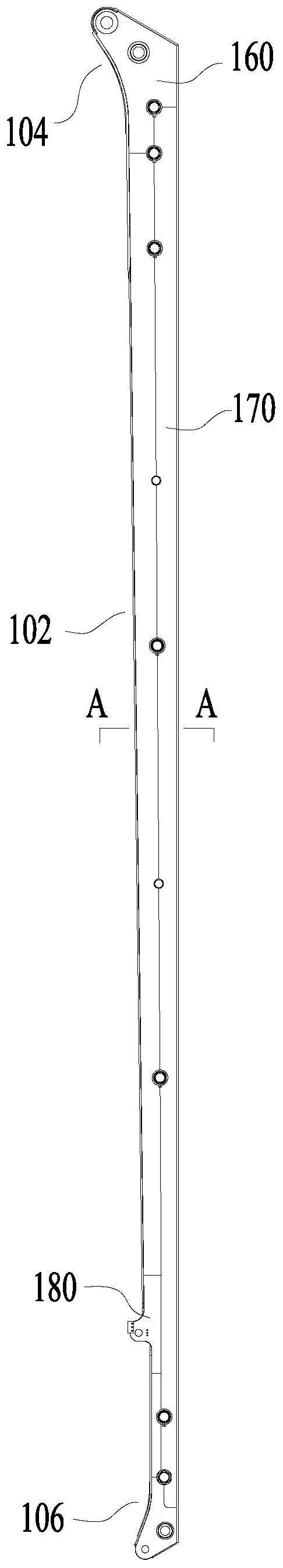
[0048] Such as image 3 and Figure 4 As shown, the present embodiment provides a boom 100, which has a frame structure, and the boom 100 includes: a top board 110, a bottom board 120, a first side board 130 and a second side board 140, and the bottom board 120 is spaced from and opposite to the top board 110 Set, the second side plate 140 and the first side plate 130 are spaced apart and opposite to each other; wherein, one side of the first side plate 130 is provided with a first bent portion 134, at least a part of the first bent portion 134 is connected to the top plate 110 Fitting and splicing each other, the other side of the first side plate 130 opposite to the first bending portion 134 is provided with a second bending portion 136, at least a part of the second bending portion 136 is bonding and splicing with the bottom plate 120; the second One side of the side plate 140 is provided with a third bending portion 144, at least a part of the third bending portion 144 is...

Embodiment 2

[0051] Such as image 3 , Figure 6 , Figure 7 and Figure 8 As shown, this embodiment provides a boom 100 . In addition to the technical features of the above-mentioned embodiments, this embodiment also includes the following technical features:

[0052] The first bending portion 134 and the second bending portion 136 are integrally formed with the first side plate 130 respectively; the third bending portion 144 and the fourth bending portion 146 are integrally formed with the second side plate 140 respectively.

[0053] In this technical solution, both ends of the first side plate 130 are respectively bent to form the first bent portion 134 and the second bent portion 136 , which improves the forming efficiency of the first side plate. Similarly, the two ends of the second side plate 140 are respectively bent to form the third bent portion 144 and the fourth bent portion 146 , which improves the forming efficiency of the second side plate 140 . Therefore, the productio...

Embodiment 3

[0055] Such as Figure 4 As shown, this embodiment provides a boom 100 . In addition to the technical features of the above-mentioned embodiments, this embodiment also includes the following technical features:

[0056] The arm frame 100 further includes: a first rib 138 disposed on the first side plate 130 and located between the first bending portion 134 and the second bending portion 136 ;

[0057] The second rib 148 is disposed on the second side plate 140 and located between the third bending portion 144 and the fourth bending portion 146 .

[0058] In this embodiment, the first rib plate 138 and the first side plate 130 are integrally configured, and the second rib plate 148 and the second side plate 140 are also integrally configured, which can not only strengthen the first side plate 130 and the second side plate 140 The structural strength can also simplify the structure and simplify the processing technology.


PUM


Abstract

The invention provides an arm rest and work equipment. The arm rest comprises a top plate, a bottom plate spaced from and opposite to the top plate, a first side plate, and a second side plate spacedfrom and opposite to the first side plate. A first bending part is mounted on one side of the first side plate, at least one part of the first bending part is attached to and spliced with the top plate, the other side of the first side plate is provided with a second bending part, at least one part of the second bending part is attached to and spliced with the bottom plate, a third bending part ismounted on one side of the second side plate, at least one part of the third bending part is attached to and spliced with the top plate, the other side, opposite to the third bending part, of the second side plate is provided with a fourth bending part, at least one part of the fourth bending part is attached to and spliced with the bottom plate, and a frame structure is defined. The arm rest isspliced through the top plate, the bottom plate, the first side plate and the second side plate, the batched production is suitable, compared with a wholly-formed mold, multiple simple molds are adopted, and alteration cost is low.

Description

technical field [0001] The present invention relates to the technical field of operating equipment, in particular, to a boom and operating equipment. Background technique [0002] At present, most of the booms of operating equipment, such as pump trucks and fire trucks, are mainly steel structures, but the booms of high-strength steel structures are too heavy. However, most of the lightweight jibs are made by integral molding of molds, which leads to the use of more complex molds, high cost, and too much investment in early process verification. In addition, if the structure of the jib made by integral molding of the mold is optimized, the mold needs to be readjusted, which is not conducive to mass production. Contents of the invention [0003] The present invention aims to solve at least one of the above technical problems. [0004] The first object of the present invention is to provide a boom. [0005] A second object of the present invention is to provide a working ...

Claims


Application Information

Patent Timeline
Patent Type & Authority Applications(China)
IPC IPC(8): E04G21/02E04G21/04B66C23/68B66C23/693A62C27/00
CPCE04G21/02E04G21/04B66C23/68B66C23/705A62C27/00E04G21/0445
Inventor 谢世惠郭汐李江波
Owner SANY AUTOMOBILE MFG CO LTD
Why Eureka
Try Eureka