Tactile sensing device based on coding hole imaging technology

A tactile sensing and coding hole technology, applied in the field of tactile sensors, can solve problems such as inability to adopt tactile sensors and increase system instability.

Active Publication Date: 2021-04-16
TSINGHUA UNIV
View PDF12 Cites 0 Cited by
  • Summary
  • Abstract
  • Description
  • Claims
  • Application Information

AI Technical Summary

Problems solved by technology

Although this structure can effectively realize close-range imaging, the lighting unit and the signal receiving unit are placed opposite to each other, so this arrangement cannot be used in the tactile sensor, and the solution must use lenses, which increases the instability of the system

Method used


Image

  • Tactile sensing device based on coding hole imaging technology
  • Tactile sensing device based on coding hole imaging technology
  • Tactile sensing device based on coding hole imaging technology

Examples


Embodiment Construction

[0032] Embodiments of the present invention are described in detail below, and examples of the embodiments are shown in the drawings, wherein the same or similar reference numerals denote the same or similar elements or elements having the same or similar functions throughout. The embodiments described below by referring to the figures are exemplary and are intended to explain the present invention and should not be construed as limiting the present invention.

[0033] The tactile sensing device based on the coding hole imaging technology proposed according to the embodiment of the present invention will be described below with reference to the accompanying drawings.

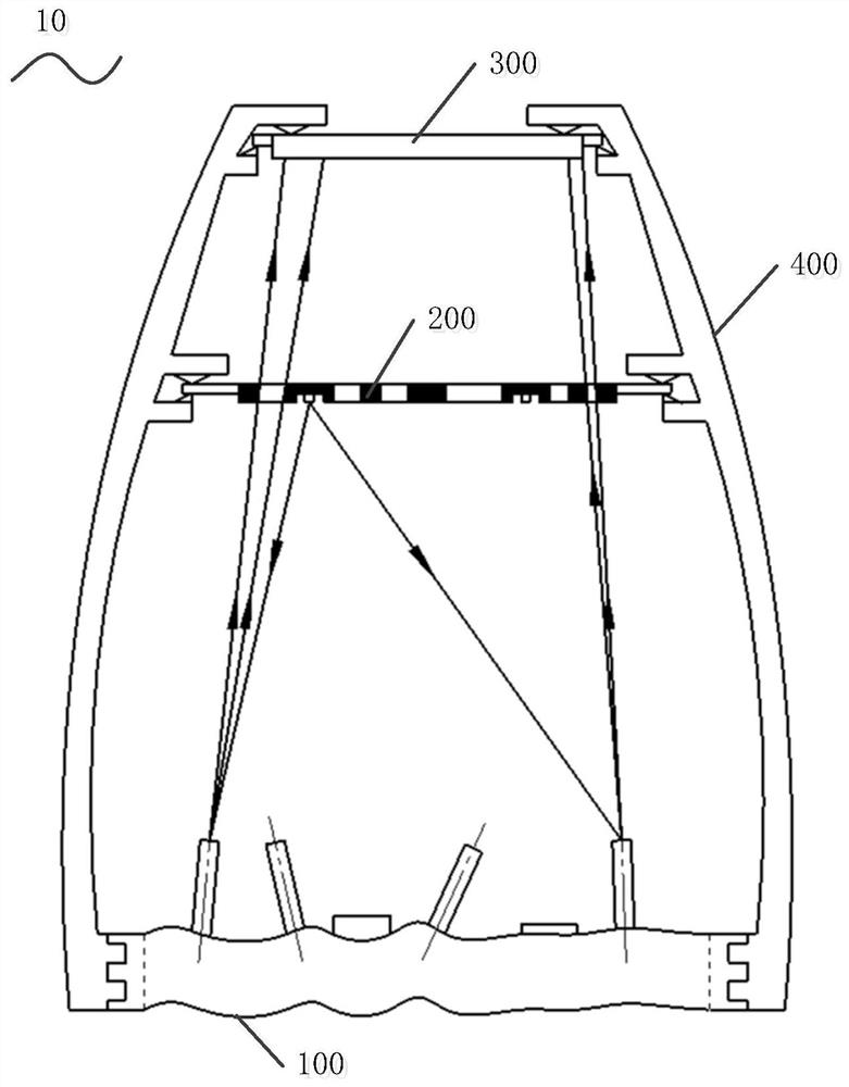
[0034] figure 1 It is a structural schematic diagram of a tactile sensing device based on coding hole imaging technology according to an embodiment of the present invention.

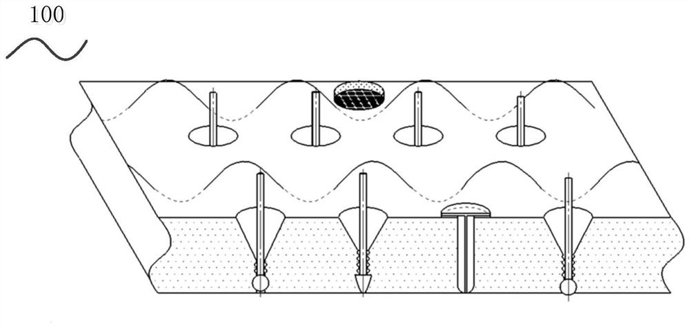
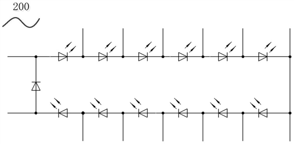
[0035] Such as figure 1 As shown, the system 10 includes: a sensing unit 100 , a coding hole unit 200 , a photoelectric conversion unit...


PUM


Abstract

The invention discloses a tactile sensing device based on coding hole imaging technology, which includes: a sensing unit, a coding hole unit, a photoelectric conversion unit and a support frame structure unit, wherein the sensing unit is arranged on the outermost layer and is used to control the touch behavior The resulting physical changes are converted into visible changes by optical means; the coded hole unit is set on the inner layer of the sensing unit, which is a plane or non-planar coded aperture plate, and the coded aperture plate is equipped with one or more optional point light sources , used to generate multiple coded aperture images through the switching of point light sources; the photoelectric conversion unit is arranged in the innermost layer, used to convert the coded aperture images into electrical signals; The conversion unit provides stable structural support. The tactile sensing device has a simple and compact structure and is easy to process.

Description

technical field [0001] The invention relates to the technical field of tactile sensors, in particular to a tactile sensing device based on coding hole imaging technology. Background technique [0002] The tactile sensor based on the optical principle is rich in information, high in precision, and has various sensing capabilities of pressure, sliding, and cold and heat. However, in related technologies, the processing and manufacturing process is complicated, the volume is relatively large, the micro-lens is more precise, and there are a series of shortcomings such as not being resistant to shocks and temperature changes, such as: [0003] Invention patent CN201410301656.7 "Optical flexible two-dimensional tangential force tactile sensor" discloses a sensor composed of a light source layer, a polymer flexible conductive layer and a photodetection layer, and the photocurrent change of a 2×2 array photodetector , to measure the magnitude and direction of the two-dimensional ta...

Claims


Application Information

Patent Timeline
Patent Type & Authority Patents(China)
IPC IPC(8): G01L1/24G01D5/26G06F3/042
CPCG01D5/26G01L1/247G06F3/042
Inventor 孙富春何竞择
Owner TSINGHUA UNIV
Why Eureka
Try Eureka