
Radar echo movement information calculation method and device

A technology of mobile information and radar echo, applied in the field of radar, can solve problems such as precipitation echo mobile information prediction

Active Publication Date: 2020-06-26
厦门市气象台 +4
View PDF14 Cites 4 Cited by
  • Summary
  • Abstract
  • Description
  • Claims
  • Application Information

AI Technical Summary

Problems solved by technology

[0004] At present, the recognition of moving speed in the radar echo extrapolation method needs to be estimated based on multiple consecutive radar detection data, and when the propagation direction of the precipitation echo changes, it is deduced based on what has happened, but it is impossible to realize the prediction of precipitation. The purpose of predicting the echo movement information

Method used

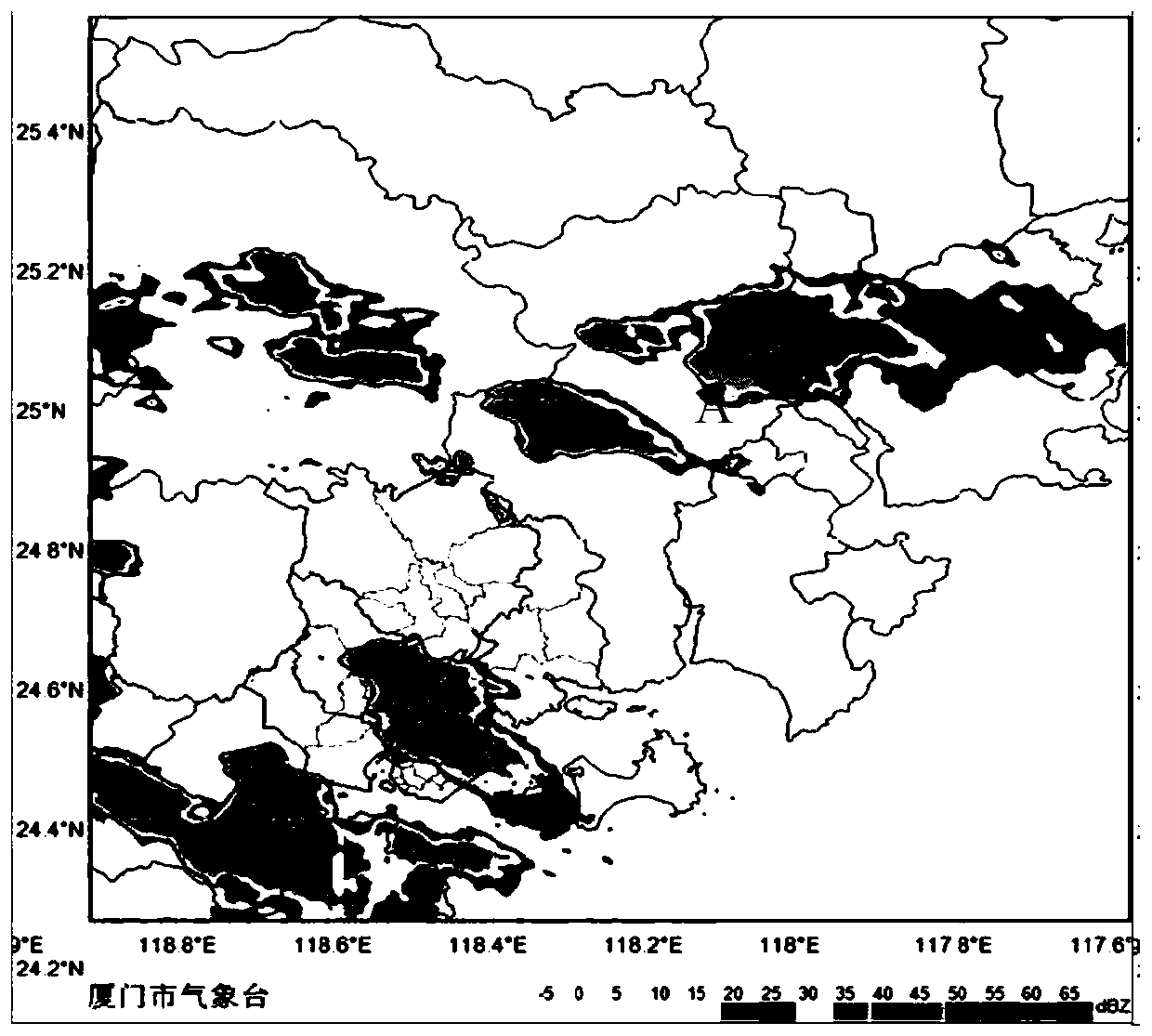
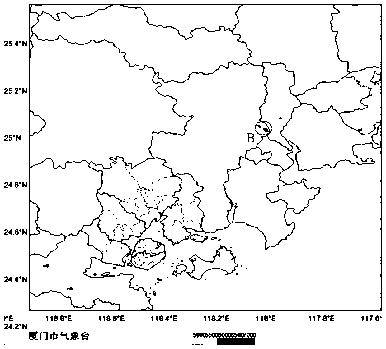

Image

  • Radar echo movement information calculation method and device
  • Radar echo movement information calculation method and device
  • Radar echo movement information calculation method and device

Examples


Embodiment 1

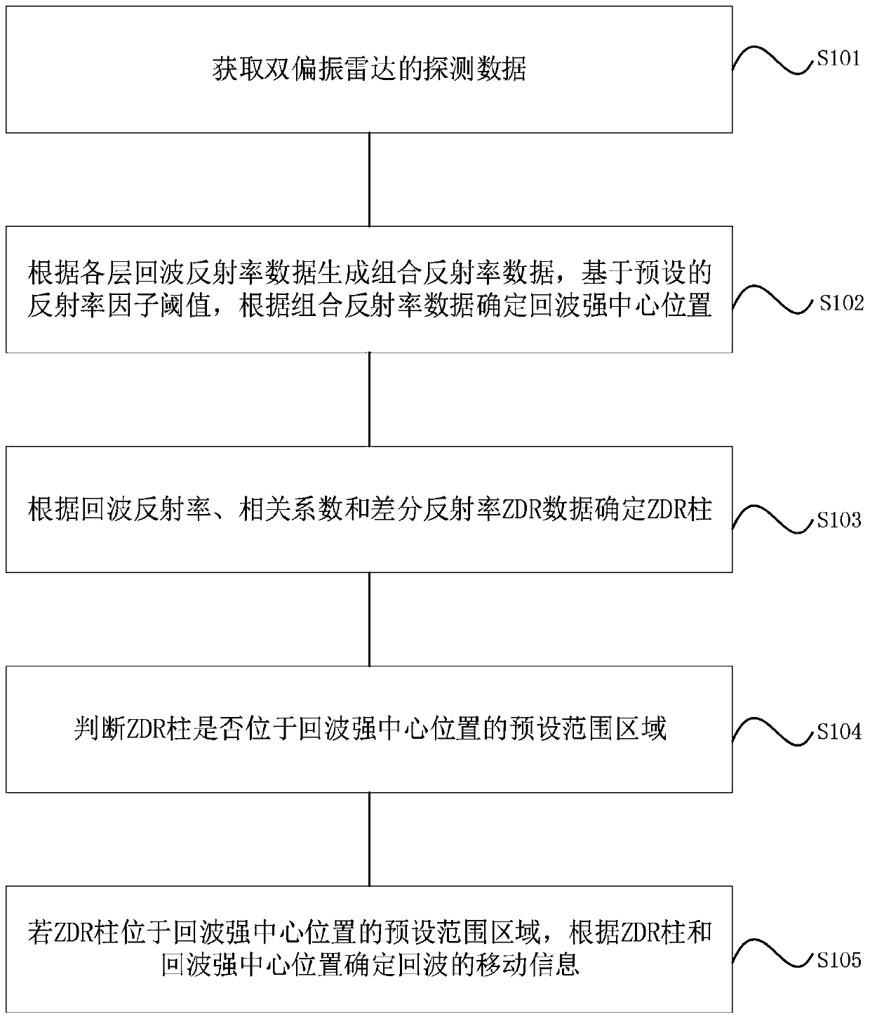
[0048] figure 1 This is a flowchart of a method for calculating radar echo movement information provided by Embodiment 1 of the present invention.

[0049] like figure 1 As shown, the method of this embodiment includes:

[0050] S101. Acquire detection data of dual-polarization radar, where the detection data includes polar coordinate data of echo reflectivity of each layer, polar coordinate data of correlation coefficient, and polar coordinate data of differential reflectivity ZDR.

[0051] When the dual-polarization radar scans the current detection position, the radar completes multiple 360° scans at different elevation angles; correspondingly, when the radar receives the echo signal, it will receive the horizontal channel within the longitude range scanned at each elevation angle. reflectivity and vertical channel reflectivity. The detection reference can include the radar's detection elevation angle and azimuth, and the azimuth is the longitude value.

[0052]S102. Ge...

Embodiment 2

[0082] The present invention also provides a device for calculating radar echo movement information, which is used to implement the above method embodiments. Figure 5 is a schematic diagram of a module of a radar echo mobile information computing device provided in Embodiment 2 of the present invention, such as Figure 5 As shown, the device includes:

[0083] The acquisition module 51 is used to acquire the detection data of the dual-polarization radar, and the detection data includes the polar coordinate data of the echo reflectivity of each layer, the polar coordinate data of the correlation coefficient, and the polar coordinate data of the differential reflectivity ZDR;

[0084] The echo reflectivity data processing module 52 is configured to generate combined reflectivity data according to the echo reflectivity data of each layer and a preset reflectivity factor threshold, and determine the echo intensity center position according to the combined reflectivity data;

[0...


PUM


Abstract

The invention relates to a radar echo movement information calculation method and device. The detection data of a double-polarization radar is obtained; generating combined reflectivity data accordingto the echo reflectivity data of each layer in the detection data; the method is based on a set reflectivity factor threshold. Calibrating the combined reflectivity data in a first plane area according to a corresponding detection position and determining an echo intensity center position; according to echo reflectivity, correlation coefficient and differential reflectivity ZDR data in the detection data, determining a ZDR column and ZDR column information in a second plane area corresponding to the detection position; and calculating the movement information of the echo according to the central position of the ZDR column and the central position of the echo intensity in the area in the contour line of the central position of the echo intensity, so as to achieve the purpose of predictingthe movement information of the precipitation echo.

Description

technical field [0001] The present invention relates to the technical field of radar, in particular to a method and device for calculating radar echo movement information. Background technique [0002] With the continuous development and progress of radar technology, it is widely used in meteorology. In addition to the original basic data (reflectivity, Doppler velocity, spectral width), meteorological radar can obtain more and more detection data, such as Dual polarization parameters. The double-bias parameter ZDR (English full name Differential Reflectivity factor) can represent the axial ratio of the droplet in the atmosphere, and under the combined action of atmospheric buoyancy and gravity, the droplet will appear flat, so it can be displayed as a positive value in the ZDR parameter . However, as the height increases, most of the water-phase particles above the zero-degree layer are ice crystals, which are displayed as negative values ​​in the ZDR parameter. [0003]...

Claims


Application Information

Patent Timeline
IPC IPC(8): G01S13/95G01S7/41
CPCG01S7/411G01S7/414G01S13/95Y02A90/10
Inventor 郑辉吴毅楠吕巧谊蒋永成陈德花赵玉春
Owner 厦门市气象台
Learn More