Unlock instant, AI-driven research and patent intelligence for your innovation.

Radar based system and method for detection of an object and generation of plots holding radial velocity data, and system for detection and classification of unmanned aerial vehicles, UAVs

A radar system and radar technology, applied in the field of radar-based systems, can solve the problem that the radar detection system cannot distinguish between UAVs, etc., and achieve the effect of optimizing the use of processing capacity and high scanning rate

Pending Publication Date: 2020-06-26
ROBIN RADAR FACILITIES BV
View PDF15 Cites 0 Cited by
  • Summary
  • Abstract
  • Description
  • Claims
  • Application Information

AI Technical Summary

Problems solved by technology

but such a radar detection system cannot distinguish between known or unknown UAVs

Method used


Image

  • Radar based system and method for detection of an object and generation of plots holding radial velocity data, and system for detection and classification of unmanned aerial vehicles, UAVs
  • Radar based system and method for detection of an object and generation of plots holding radial velocity data, and system for detection and classification of unmanned aerial vehicles, UAVs
  • Radar based system and method for detection of an object and generation of plots holding radial velocity data, and system for detection and classification of unmanned aerial vehicles, UAVs

Examples


Embodiment Construction

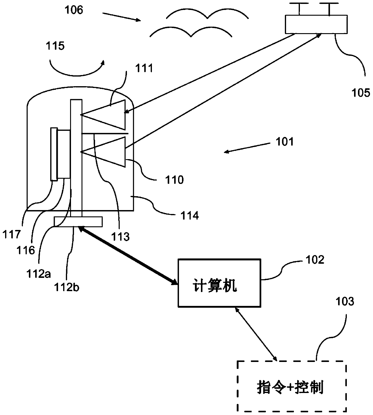
[0231] Figure 1a is a schematic block diagram showing a basic structure of a scanning radar system according to an exemplary embodiment. The system includes a frequency modulated continuous wave (FMCW) radar system 101 electrically connected to a computer system 102 . The generated output data can be communicated to the external command and control system 103, where the data can be communicated by real-time data streaming, where eg Extensible Markup Language (XML) can be used for streaming.

[0232] The FMCW radar system 101 comprises a transmitting horn antenna 110 and a receiving horn antenna 111 , wherein a split plane 113 is arranged between the two antennas 110 and 111 to prevent spurious reflections. The antennas 110 , 111 are surrounded by a radome 114 made of plastic, which produces no or very low reflections of radar waves, so that Doppler shift interference is avoided. The split plane 113 is arranged very close to the radome 114, also to prevent spurious reflection...


PUM


Abstract

A Frequency Modulated Continuous Wave, FMCW, radar system is provided. The radar system comprises one or more antennas configured to transmit and receive FMCW radar wave signals for scanning for objects within a full circular detection coverage range, and processing circuitry configured to provide scan data based on transmitted and received FMCW radar signals and azimuth position of the antenna(s). In a first aspect, the processing circuitry is configured to generate first type radar plots, where each first type radar plot holds range, radial velocity and return energy data for one or more detected objects, and configured to generate second type radar plots, where each second type radar holds azimuth, range and return energy data for one or more detected objects. In the first aspect, the processing circuitry is also configured to generate full data type radar plots by combining first and second type radar plots having corresponding range data, whereby each full data type radar plot holds azimuth, range, radial velocity and return energy data for one or more detected objects. In a second aspect, the processing circuitry is configured to generate full data type radar plots based on obtained scan data, and the processing circuitry is further configured to select irregular type radar plots from full data type radar plots, where the irregular type radar plots have velocity data representing positive and negative radial velocities within an observed radial velocity range. The processing circuitry may also be configured to generate object tracks or unmanned aerial vehicle, UAV, tracks, where each object / UAV track is based on at least two irregular type radar plots. In a third aspect, then for the plots of a generated object / UAV track, the processing circuitry is configured todetermine an outer energy sum of return energies for range cells representing positive and negative radial velocity signals within a first and a second outer radial velocity range, and to determine acenter energy sum of return energies for range cells representing radial velocity signals within a center range of the observed radial velocity range, and / or a total energy sum of return energies of range cells representing all observed radial velocity signals. In a fourth aspect, there is provided an unmanned aerial vehicle, UAV, system, which UAV system comprises a control station for controlling a first co-operating unmanned aerial vehicle, UAV, and a radar system configured to scan for objects within a detection coverage range and to provide scan data indicative of objects detected withinthe coverage range. The first UAV may be provided with a transponder holding identification information, ID, and the first UAV and the control station may be configured for exchanging transponder data.

Description

technical field [0001] The present disclosure relates to radar-based systems and methods for scanning and detecting objects using a Frequency Modulated Continuous Wave (FMCW) radar system, and more particularly to generating maps that include radial velocity data. The generated maps can be used to track and classify detected objects including unmanned aerial vehicles (UAVs). [0002] The present disclosure also relates to a system for detecting and classifying unmanned aerial vehicles (UAVs). Classification of UAVs can be used to differentiate between several detected UAVs. Background technique [0003] The number of small unmanned aerial vehicles (UAVs) available for civilian use has increased significantly in recent years. These platforms can be used privately for leisure and filming, but also for applications such as agricultural and environmental monitoring, surveillance and disaster response. However, small UAVs can also be misused for anti-social, unsafe, and even c...

Claims


Application Information

Patent Timeline
Patent Type & Authority Applications(China)
IPC IPC(8): G01S7/41G01S13/536G01S13/32G01S13/72
CPCG01S7/415G01S13/32G01S13/536G01S13/72G01S13/933G01S13/584G01S13/723B64U2101/30
Inventor 沃特·谢耶尔赫尔本·帕克尔特
Owner ROBIN RADAR FACILITIES BV
Features
  • R&D
  • Intellectual Property
  • Life Sciences
  • Materials
  • Tech Scout
  • Unparalleled Data Quality
  • Higher Quality Content
  • 60% Fewer Hallucinations
Learn More