Mechanical arm and surgery robot

A robotic arm and medical device technology, applied in the field of medical devices, can solve the problems of heavy mechanical arm structure, low stability, and poor flexibility, and achieve the effects of reducing difficulty, small overall size, and easy installation and use

Active Publication Date: 2020-06-30
SHANGHAI MICROPORT MEDBOT (GRP) CO LTD
View PDF9 Cites 16 Cited by
  • Summary
  • Abstract
  • Description
  • Claims
  • Application Information

AI Technical Summary

Problems solved by technology

[0005] The purpose of the present invention is to provide a mechanical arm and a surgical robot, which can avoid the fatigue caused by the surgeon's long-term operation and the arm tremor of the surgeon during the operation, thereby improving the accuracy, stability and safety of the operation. Solve the problems of bulky structure, low precision, poor flexibility and low stability of the robotic arm

Method used


Image

  • Mechanical arm and surgery robot
  • Mechanical arm and surgery robot
  • Mechanical arm and surgery robot

Examples


Embodiment 1

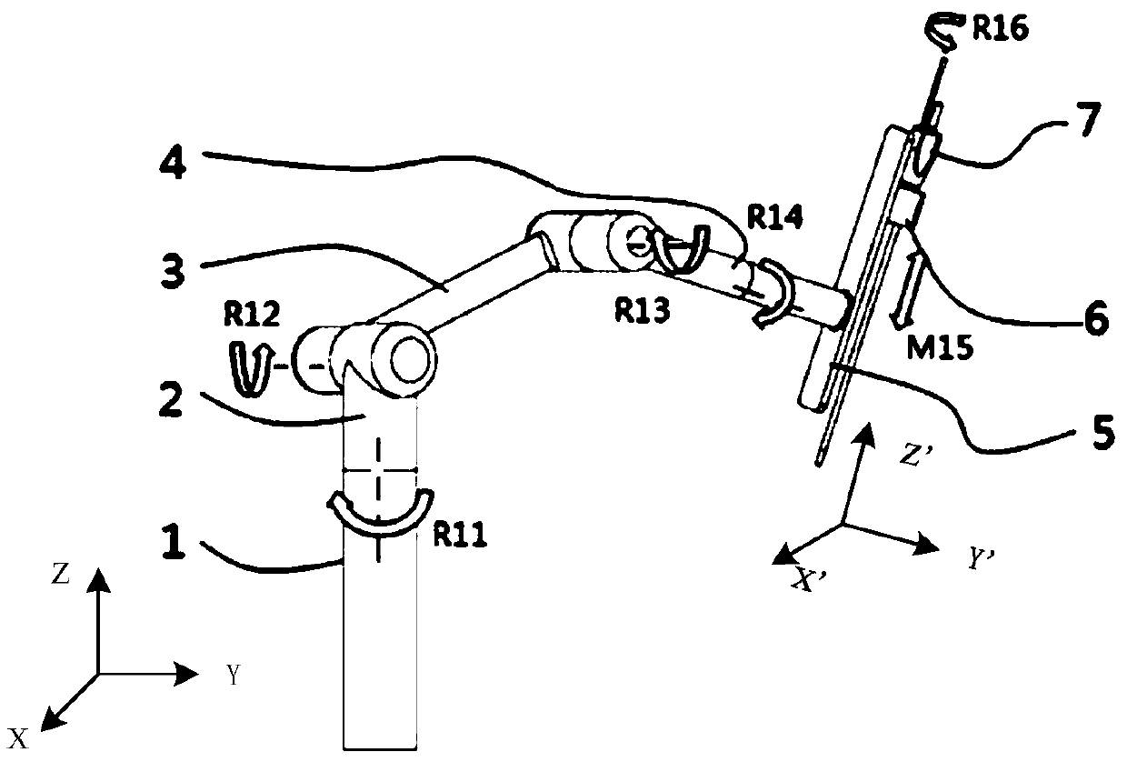
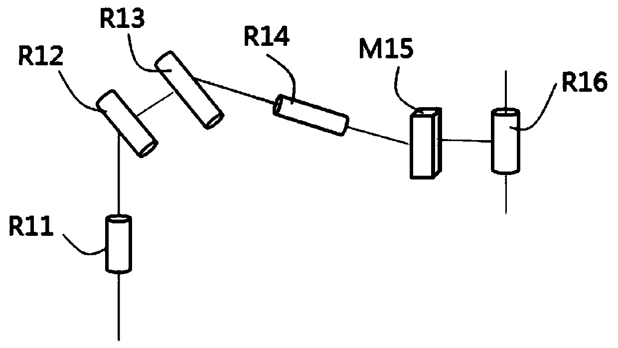
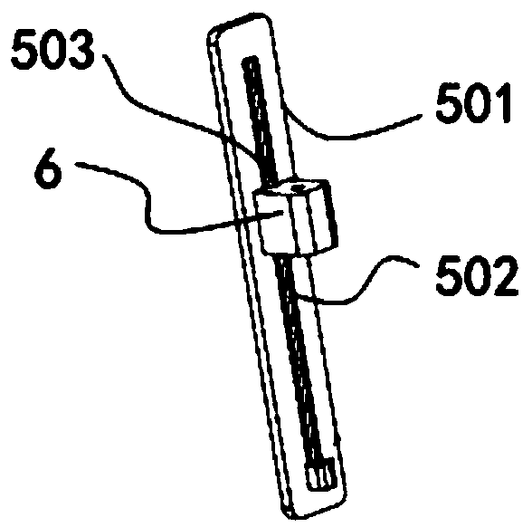
[0059] Please refer to Figure 1 to Figure 5 ,in, figure 1 It is a schematic structural diagram of the robotic arm provided in Embodiment 1 of the present invention, figure 2 yes figure 1 The schematic diagram of the degrees of freedom of the manipulator shown, image 3 It is a schematic diagram of the connection between the telescopic structure and the endoscope clamping structure provided by Embodiment 1 of the present invention, Figure 4 It is a schematic diagram of the surgical robot adjusting the endoscope in Embodiment 1 of the present invention, Figure 5 It is a schematic diagram of the endoscope driven by the surgical robot to swing in the first embodiment of the present invention.

[0060] Such as figure 1 and figure 2 As shown, the first embodiment provides a mechanical arm for clamping medical instruments, the end of which is connected to the endoscope 7, specifically connected to the endoscope 7 in a detachable manner, so as to adjust the space of the end...

Embodiment 2

[0074] Please refer to Figure 6 to Figure 8 ,in, Figure 6 It is a schematic structural diagram of the mechanical arm provided in Embodiment 2 of the present invention, Figure 7 yes Figure 6 A schematic diagram of the joints of the robotic arm shown, Figure 8 It is a schematic diagram of the endoscope driven by the surgical robot to swing in the second embodiment of the present invention.

[0075] The mechanical arm of the second embodiment of the present invention is basically the same as that of the first embodiment, the same parts will not be described, and only the differences will be described below.

[0076] Such as Figure 6 and Figure 7 As shown, the mechanical arm also includes a fourth connecting rod 8, the distal end of the fourth connecting rod 8 is connected to the telescopic structure 5 through the third swing joint R17, the proximal end is connected to the second rotating joint R14, and the second rotating joint R14 is connected with the far end of th...

Embodiment 3

[0083] This embodiment provides an exemplary method for controlling the movement of the endoscope connected to the end of the above-mentioned robotic arm around a remote center of motion (Remote Center of Motion). Based on the configuration of the robotic arm in the first embodiment, the robotic arm includes a control module, a position acquisition module, and a drive module (not shown). The position acquiring module, the driving module are connected in communication with the control module. The position acquiring module is used to acquire each joint (that is, the first rotational joint R11, the first swing joint R12, the second swing joint R13, the second rotational joint R14, the moving joint M15 and the rotation joint R16 in the first embodiment) the current location of . The driving module is used to drive the above-mentioned joints to move. The control module includes an active mode and a passive mode. In this active mode, the control module controls the movement of ea...


PUM


Abstract

The invention provides a mechanical arm and a surgery robot. The tail end of the mechanical arm is used for grasping a medical apparatus. The mechanical arm comprises a first rotating joint, a first swinging joint, a second swinging joint, a second rotating joint, a moving joint, and an autorotation joint for realizing the autorotation of the medical apparatus, which are sequentially distributed from the near end to the far end. According to the mechanical arm disclosed by the invention, through the cooperation of the six joints, the adjustment of the space position and the posture of the medical apparatus can be realized, and the six joints can move around a long-distance movement center. Compared with the prior art, the mechanical arm disclosed by the invention is small in whole dimension, light in quality, convenient to mount and use; and in addition, through the moving joint and the autorotation joint, an endoscope is driven to move and autorotate, so that a doctor can convenientlyand independently complete surgery operations and endoscope grasping, the difficulty of the surgery operations is reduced, and the waste of human resources is avoided.

Description

technical field [0001] The invention relates to the field of medical instruments, in particular to a mechanical arm and a surgical robot. Background technique [0002] Endoscopic surgery is a major advancement in the history of medicine, but most of the endoscopic operations still require specialized medical staff to control the endoscope. For many hospitals, there is often a shortage of manpower, including more experienced mirror holders. For this reason, when observing certain parts of the abdominal cavity, the mirror holder maintains a posture for a long time. The arm is often tired due to soreness, which makes it difficult to hold the mirror and affects the operation. [0003] As a result, the Da Vinci surgical robot appeared abroad, and the endoscope was controlled by a robotic arm. Although the da Vinci surgical robot has many advantages, the entire robotic arm system is relatively bulky. Moreover, in order to facilitate preoperative adjustment, the passive arm need...

Claims


Application Information

Patent Timeline
Patent Type & Authority Applications(China)
IPC IPC(8): A61B34/00A61B34/35
CPCA61B34/70A61B34/35A61B2034/302
Inventor 李涛倪飞箭何超
Owner SHANGHAI MICROPORT MEDBOT (GRP) CO LTD
Why Eureka
Try Eureka