Supercharge Your Innovation With Domain-Expert AI Agents!

Micro-channel reactor with energy storage structure

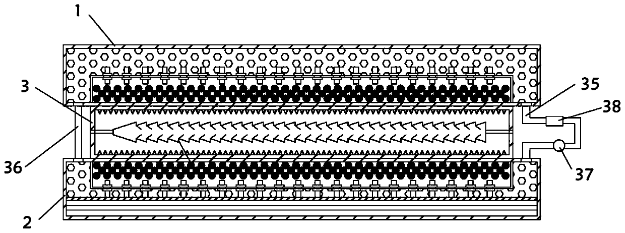
A micro-channel reactor, a technology for micro-channel reaction, applied in chemical/physical/physical-chemical reactors, chemical instruments and methods, chemical/physical/physical-chemical processes, etc. energy structure, increase the load of heat exchange equipment, etc., to achieve the effect of saving heat exchange equipment load, improving reaction effect, and uniform heat transfer

Active Publication Date: 2020-06-30
QINGDAO UNIV OF SCI & TECH
View PDF11 Cites 3 Cited by
  • Summary
  • Abstract
  • Description
  • Claims
  • Application Information

AI Technical Summary

Problems solved by technology

[0003] When the existing microchannel reactor is used, it is necessary to heat the upper and lower ends of the microchannel reaction plate or the left and right ends. The heat transfer generally adopts the way of thermal fluid circulation. The existing microchannel reactor is introduced from the outside. The heat transfer medium requires The relatively long external pipeline leads to relatively large energy loss, requires a large amount of heat transfer fluid, and has a large load on heat exchange equipment
Moreover, the existing microchannel reactors do not have an energy storage structure. When the reaction heat release or heat absorption is large, the flow rate of the heat exchange medium is required to be relatively fast, which increases the load on the heat exchange equipment.
When the flow rate of the heat exchange medium is slow, the generated heat cannot be quickly and promptly discharged, resulting in large fluctuations in the reaction temperature, reducing the selectivity of the target product, and producing more by-products

Method used


Image

  • Micro-channel reactor with energy storage structure
  • Micro-channel reactor with energy storage structure
  • Micro-channel reactor with energy storage structure

Examples


Embodiment Construction

[0037] The following will clearly and completely describe the technical solutions in the embodiments of the present invention with reference to the accompanying drawings in the embodiments of the present invention. Obviously, the described embodiments are only some, not all, embodiments of the present invention. Based on the embodiments of the present invention, all other embodiments obtained by persons of ordinary skill in the art without making creative efforts belong to the protection scope of the present invention.

[0038] In describing the present invention, it should be understood that the terms "center", "longitudinal", "transverse", "length", "width", "thickness", "upper", "lower", "front", " Orientation indicated by rear, left, right, vertical, horizontal, top, bottom, inside, outside, clockwise, counterclockwise, etc. The positional relationship is based on the orientation or positional relationship shown in the drawings, and is only for the convenience of describin...


PUM


Abstract

The invention discloses a micro-channel reactor with an energy storage structure, wherein the micro-channel reactor comprises an upper heating plate, a lower heating plate and a micro-channel reactionplate arranged between the upper heating plate and the lower heating plate, and the upper heating plate and the lower heating plate are filled with a heat conduction liquid; the micro-channel reaction plate is of a hollow cavity structure, a micro-channel reaction tube is arranged in the micro-channel reaction plate, the micro-channel reaction tube is integrally formed by splicing a plurality oftrapezoidal tubes, a clamping foot protruding inwards is arranged at the joint of each two trapezoidal tubes, and a flow limiting plate extending into each tube is integrally formed at one end of eachclamping foot. The reactor is uniform in internal heat transfer, uniform heating of the micro-channel reaction plate can be guaranteed, the energy storage layer is arranged, energy loss can be reduced, meanwhile, the mixing effect can be improved through the arrangement of the trapezoidal tubes, the clamping feet and the flow limiting plates, and sufficient reaction is facilitated.

Description

technical field [0001] The invention relates to the technical field of microchannel reactors, in particular to a microchannel reactor with an energy storage structure. Background technique [0002] A microchannel reactor is a three-dimensional structural element that can be used for chemical reactions and is fabricated from a solid matrix by means of special micromachining techniques. Microchannel reactors generally contain small channel sizes (less than 500 [mu]m in equivalent diameter) and a multiplicity of channels in which fluids flow and where desired reactions are required to take place. This leads to very large surface area / volume ratios in microstructured reaction devices. [0003] When the existing microchannel reactor is used, it is necessary to heat the upper and lower ends of the microchannel reaction plate or the left and right ends, and the heat transfer generally adopts the way of thermal fluid circulation. The existing microchannel reactor is introduced from...

Claims


Application Information

Patent Timeline
Patent Type & Authority Applications(China)
IPC IPC(8): B01J19/00
CPCB01J19/0093B01J19/0013B01J19/002
Inventor 杨安明岳金彩杨霞郑世清秦利涛周波周东健
Owner QINGDAO UNIV OF SCI & TECH
Features
  • R&D
  • Intellectual Property
  • Life Sciences
  • Materials
  • Tech Scout
  • Unparalleled Data Quality
  • Higher Quality Content
  • 60% Fewer Hallucinations
Learn More