
Automatic lathe

An automatic lathe and shaft transmission technology, which is applied in the direction of automatic lathes/semi-automatic lathes, turning equipment, turning equipment, etc., can solve the problems of troublesome operation and increase the workload of staff, and achieve simple and convenient operation and avoid entanglement of debris and the effect of impurities

Pending Publication Date: 2020-06-30
山东新景机械有限公司
View PDF0 Cites 0 Cited by
  • Summary
  • Abstract
  • Description
  • Claims
  • Application Information

AI Technical Summary

Problems solved by technology

[0006] The purpose of the present invention is to provide an automatic lathe to solve the problem that the traditional numerical control automatic lathes on the market cannot perform high-pressure processing on materials when processing materials proposed by the above-mentioned background technology. To clean up, the operation is more troublesome, and the problem of increasing the workload of the staff

Method used


Image

  • Automatic lathe
  • Automatic lathe
  • Automatic lathe

Examples


Embodiment Construction

[0026] The following will clearly and completely describe the technical solutions in the embodiments of the present invention with reference to the accompanying drawings in the embodiments of the present invention. Obviously, the described embodiments are only some, not all, embodiments of the present invention. Based on the embodiments of the present invention, all other embodiments obtained by persons of ordinary skill in the art without making creative efforts belong to the protection scope of the present invention.

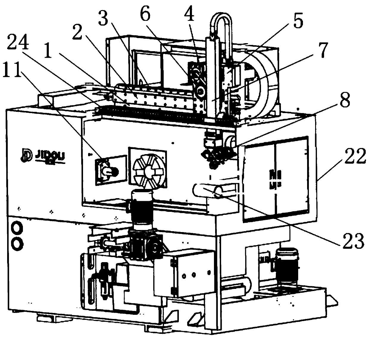
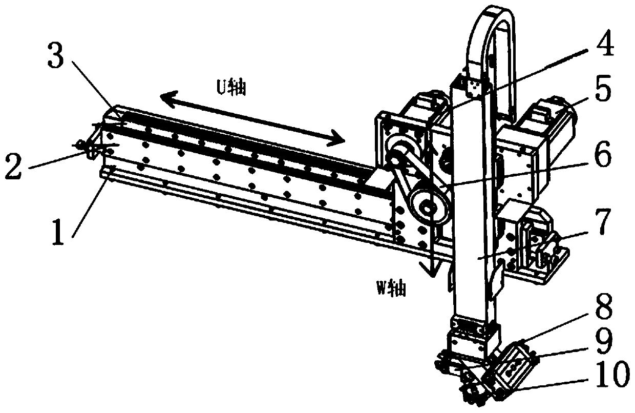
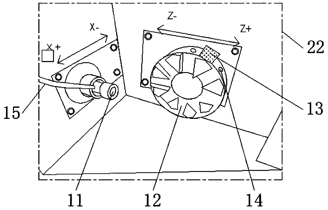
[0027] see Figure 1-6 , the present invention provides a technical solution: an automatic lathe, including U-axis beam 1, U-axis guide rail 2, U-axis rack 3, U-axis motor 4, W-axis motor 5, U-axis transmission group 6, W-axis transmission Group 7, rotary claw cylinder 8, finished claw 9, raw material claw 10, claw main body 11, turret main body 12, pressing jig 13, high pressure nozzle 14, flushing pipe 15, Z servo axis motor 16, turret hydraulic cylinder 17...


PUM


Abstract

The invention discloses an automatic lathe which comprises a U shaft cross beam, a U shaft guide rail, a U shaft rack, a U shaft motor and a W shaft motor, wherein the U shaft guide rail is fixed above the U shaft cross beam through a screw; the U shaft rack is mounted in the U shaft guide rail; the U shaft motor is fixed on the outer side of the right end of the U shaft guide rail through the screw; a U shaft transmission group is connected with the outer side of the output end of the U shaft motor; a W shaft transmission group is arranged on the right side of the U shaft transmission group;the W shaft motor is mounted at the rear end of the W shaft transmission group; a finished product claw is mounted at the bottom end of the W shaft transmission group; a raw material claw is mounted on the right side of the finished product claw; a rotating claw air cylinder is mounted above the raw material claw; a machine tool main body is fixed below the U shaft cross beam; a clamping claw mainbody is arranged on the front side face of the machine tool main body; and a knife tower main body is arranged on the right side of the clamping claw main body. The automatic lathe is provided with ahigh pressure lubricating nipple, so that high pressure treatment on the product surface is facilitated, and chippings and impurities on the product surface can be conveniently removed.

Description

technical field [0001] The invention relates to the technical field of automatic lathes, in particular to an automatic lathe. Background technique [0002] Automatic lathe is a kind of equipment used in the processing and manufacturing of precision parts such as copper, aluminum, iron and plastic. The automatic lathe can not only improve work efficiency but also improve the quality of work. There are CNC automatic lathes, pneumatic automatic lathes and centering type automatic lathe, etc., but there are still some shortcomings in the use of automatic lathes, such as: [0003] 1. The traditional CNC automatic lathe cannot process the material with high pressure when processing the material, so that not only the surface of the material will adhere to more debris during the processing process, but also affect the quality of material processing; [0004] 2. During the processing, the surface of the clamping mechanism of the automatic lathe will adhere to some debris or other im...

Claims


Application Information

Patent Timeline
IPC IPC(8): B23B7/00B23B15/00B23B25/00B23B31/103B23Q11/00
CPCB23B7/00B23B25/00B23B31/103B23Q11/0042B23Q11/0075B23Q7/00B23Q7/04
Inventor 杨冰王荣山许文杰孟斌唐文宇孙利民王鹏辉
Owner 山东新景机械有限公司
Features
  • Generate Ideas
  • Intellectual Property
  • Life Sciences
  • Materials
  • Tech Scout
  • Unparalleled Data Quality
  • Higher Quality Content
  • 60% Fewer Hallucinations
Learn More