Method for prefabricating pipe joints of immersed tube tunnel

An immersed tube tunnel and tube section technology is applied in the field of immersed tube section prefabrication, which can solve the problems of low practicability of prefabricated tube section scheme, complex tunnel construction engineering conditions, strict navigation requirements in surrounding waters, etc., so as to reduce dry docking. Depth requirements, flexible transportation methods, and the effect of saving rental costs

Pending Publication Date: 2020-06-30
CHINA RAILWAY TUNNEL SURVEY & DESIGN INST +1
View PDF7 Cites 3 Cited by
  • Summary
  • Abstract
  • Description
  • Claims
  • Application Information

AI Technical Summary

Problems solved by technology

[0002] The use of deep foundation pit dry dock or land factory method dry dock to prefabricate tunnel pipe joints of immersed pipe method has become the mainstream of construction technology of this construction method in China after long-term practice, summary and improvement. It is also the most widely used. Its advantage is that it saves the construction period and the construction risk is low. The disadvantage is that it needs to occupy a large area of ​​land, the temporary cost is high, and the environmental cost is high.
As a prefabricated platform, semi-submersible barges, although started early, are not widely adaptable due to factors such as the limitation of the width of the hull itself, strict requirements for navigation in surrounding waters, and high rents, and can only be considered as specific cases.
[0003] With the rapid development of dense cities, the conditions of tunnel construction projects will become more and more complex, especially in the case of tight land resources, difficulties in land acquisition, and increasingly high requirements and conditions for environmental protection, deep foundation pits, dry docks or land The practicability of the factory method prefabricated pipe joint scheme will become lower and lower

Method used


Image

  • Method for prefabricating pipe joints of immersed tube tunnel
  • Method for prefabricating pipe joints of immersed tube tunnel
  • Method for prefabricating pipe joints of immersed tube tunnel

Examples


Embodiment Construction

[0035] In order to better understand the purpose, structure and function of the present invention, a method for prefabricating immersed tunnel pipe joints according to the present invention will be further described in detail below in conjunction with the accompanying drawings.

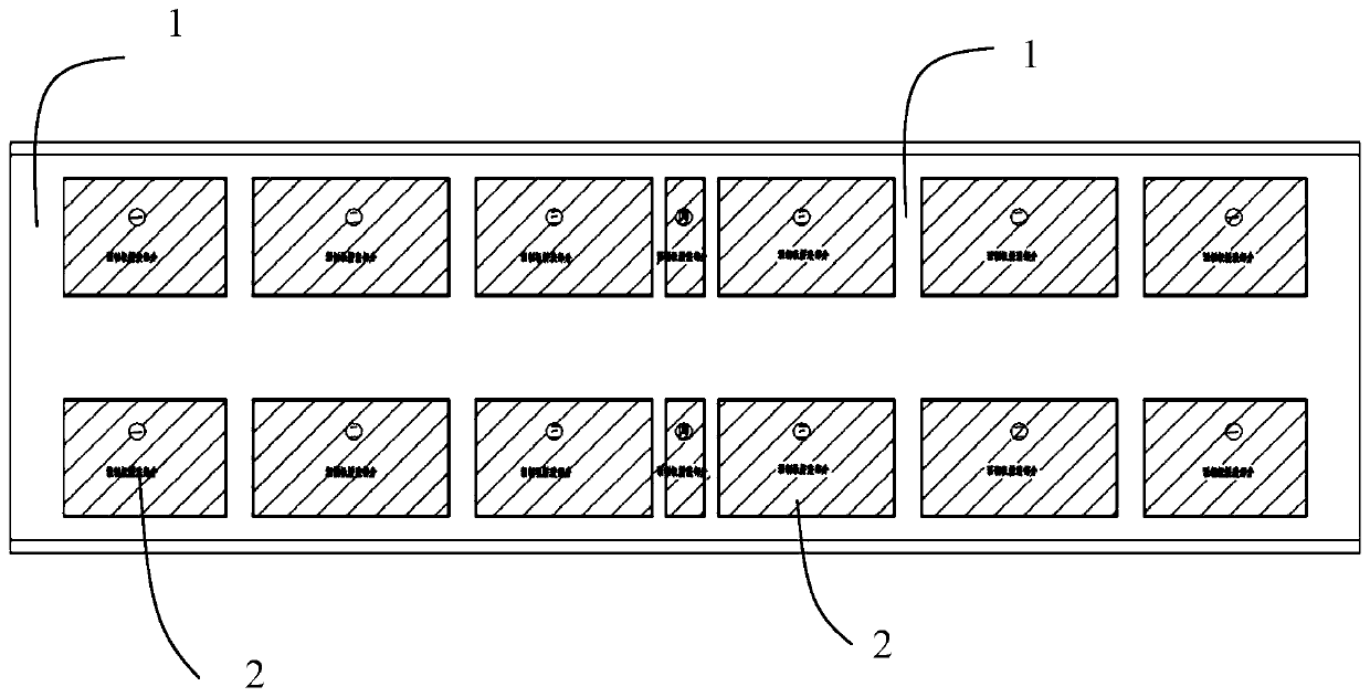
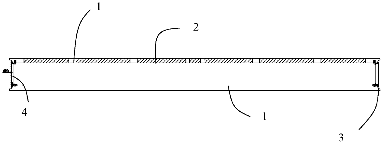
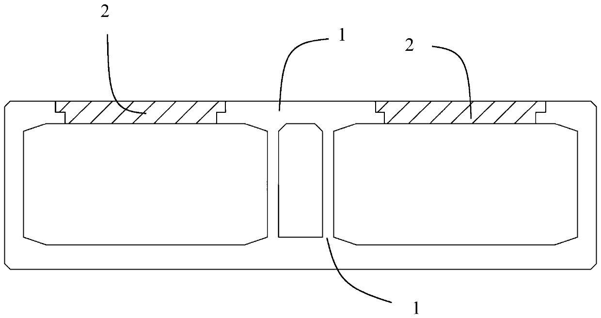
[0036] Such as Figure 1 to Figure 4 As shown, it is shown as a method for prefabricating pipe joints of an immersed tube tunnel of the present invention, and the specific steps are as follows:

[0037] Step 1, tie steel bars and pour pipe joint 1 in shallow dry dock.

[0038] Wherein, when pouring the pipe joint 1, except for the opening area of ​​the prefabricated slab 2 on the pipe joint 1, the rest are all prefabricated in the shallow dry dock.

[0039] Among them, the prefabricated platform of the shallow dry dock can use a newly excavated foundation pit, and the depth is determined according to the requirements of the floating transportation of the pipe joints, so as to reduce the amount of dre...


PUM


Abstract

The invention discloses a method for prefabricating pipe joints of an immersed tube tunnel. The method comprises the following steps that 1, steel bars are bound in a shallow dry dock, and the pipe joints are poured; 2, a steel end shell, a steel end sealing wall and a guiding device are arranged at the two ends of each pipe joint; 3, a waterproof layer of each pipe joint is constructed; 4, prefabricated plates are prefabricated in a prefabricated site beside an assembling platform; 5, a dock door is opened, the pipe joints are conveyed to the assembling platform in a floating mode, and a hoisting system is arranged on the assembling platform; 6, the prefabricated plates are hoisted to the corresponding positions of the pipe joints through the hoisting system; 7, the waterproof layers areapplied above the prefabricated plates; and 8, the pipe joints are dragged to designated positions for reassembling and then sinking. According to the method, the pipe joint floating process is shallow in draft depth, the temporary project is little, the dredging amount in water or dredging is not needed, the environment influence is small, and streamlined operation can be carried out.

Description

technical field [0001] The invention relates to the technical field of immersed tube tunnels, in particular to a method for prefabricating pipe joints of immersed tube tunnels. Background technique [0002] The use of deep foundation pit dry dock or land factory method dry dock to prefabricate tunnel pipe joints of immersed pipe method has become the mainstream of construction technology of this construction method in China after long-term practice, summary and improvement. It is also the most widely used. Its advantage is that it saves the construction period and has low construction risk. The disadvantage is that it needs to occupy a large area of ​​land, the temporary cost is high, and the environmental cost is high. As a prefabricated platform, semi-submersible barges started earlier, but due to factors such as the width of the hull itself, strict requirements for navigation in surrounding waters, and high rents, they do not have wide adaptability and can only be conside...

Claims


Application Information

Patent Timeline
Patent Type & Authority Applications(China)
IPC IPC(8): E02D29/073B28B23/02
CPCB28B23/02E02D29/073E02D2250/0023
Inventor 贺维国曾珂吕洋邢永辉周丽芳于勇陈国燃罗青胡斌李彬
Owner CHINA RAILWAY TUNNEL SURVEY & DESIGN INST
Why Eureka
Try Eureka