Environment-friendly waste gas combustion furnace

A waste gas combustion and environmental protection technology, applied in the direction of combustion method, combustion type, incinerator, etc., can solve the problems of corrosive equipment, unreasonable design, poor waste gas treatment effect, etc., and achieve good combustion effect

Inactive Publication Date: 2020-06-30
窦义芳
View PDF0 Cites 1 Cited by
  • Summary
  • Abstract
  • Description
  • Claims
  • Application Information

AI Technical Summary

Problems solved by technology

The existing waste gas treatment equipment for the harmless treatment of sick and dead animals has the following problems: first, the overall structure is complicated, the design is unreasonable, and the effect on waste gas treatment is not good; In the combustion chamber, long-term use will accumulate smo

Method used


Image

  • Environment-friendly waste gas combustion furnace
  • Environment-friendly waste gas combustion furnace
  • Environment-friendly waste gas combustion furnace

Examples


Embodiment 1

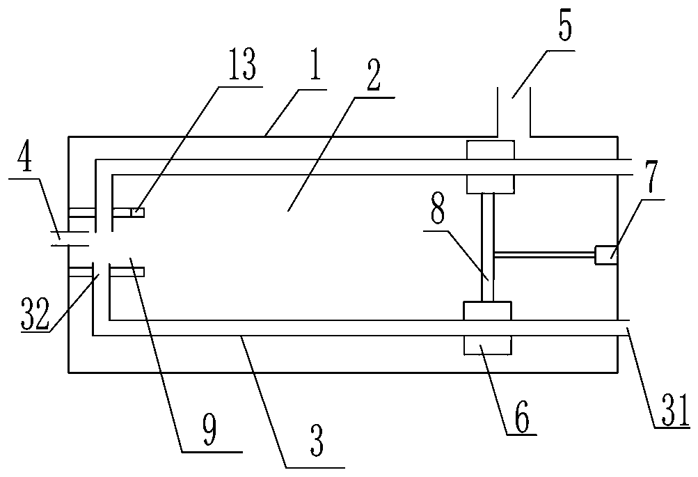
[0030] Such as figure 1 and image 3 As shown, the present invention discloses an environment-friendly waste gas combustion furnace, which includes a furnace body 1, which encloses a combustion chamber 2, and a waste gas preheating pipe 3 is arranged in the combustion chamber 2. The waste gas preheating pipe 3 is arranged along the length of the furnace body 1. One end of the waste gas preheating pipe 3 is provided with a preheating pipe waste gas inlet 31, and the preheating pipe waste gas inlet 31 passes through the furnace body 1, and the other end is provided with a preheating pipe. The pipe exhaust gas outlet 32 ​​and the preheating pipe exhaust gas outlet 32 ​​are located inside the combustion chamber 2 .

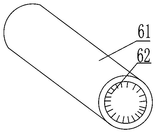
[0031] The exhaust gas preheating pipe 3 is provided with a dust removal brush 6 that can slide along the exhaust gas preheating pipe 3 , and the dust removal brush 6 is sleeved on the exhaust gas preheating pipe 3 .

[0032] The furnace body 1 is provided with a ga...

Embodiment 2

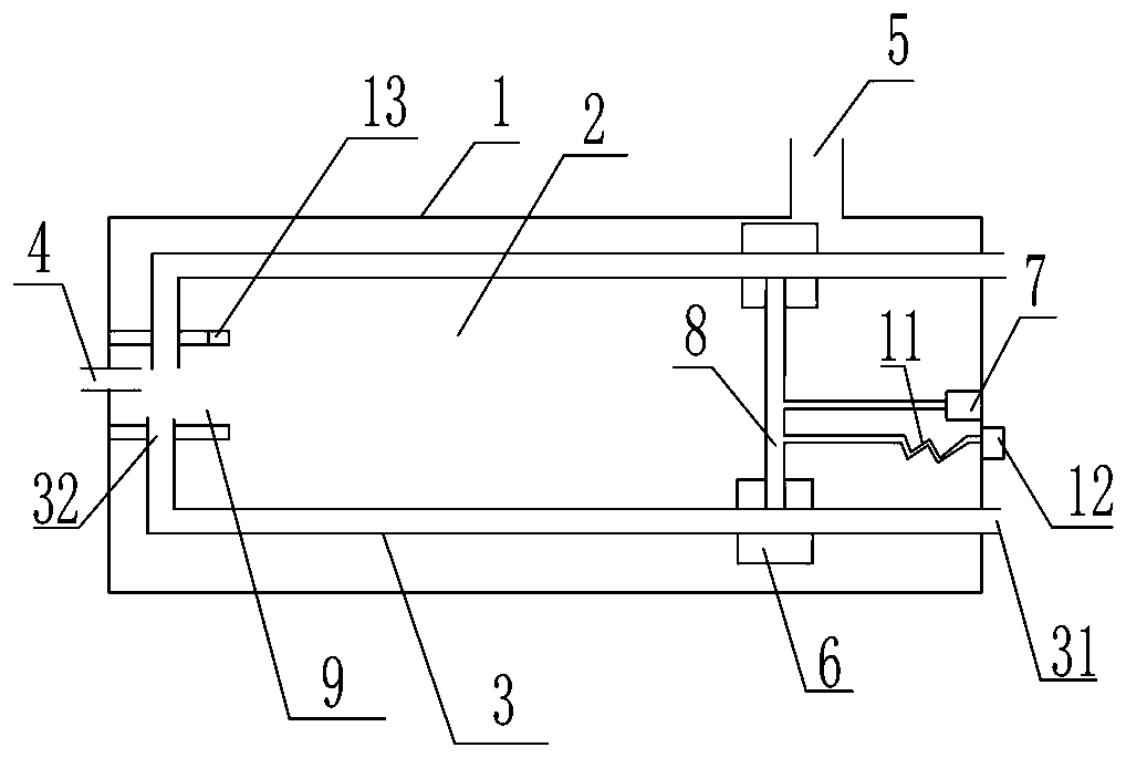
[0042] Such as Figure 4As shown, in order to fully mix the gas and the preheated exhaust gas, and then make the combustion more complete, on the basis of Embodiment 1, a further improvement is made. The end of the furnace body 1 provided with the gas inlet 4 is provided with a gas mixing chamber 9, The chamber wall of the gas mixing chamber 9 includes a part of the furnace body 1 and a side wall fixedly connected with the furnace body 1, and the side wall is surrounded by a circular tubular structure or a tubular rectangular parallelepiped structure. Of course, the structure of the combustion chamber can also be in other shapes. Both the gas inlet 4 and the exhaust gas outlet 32 ​​of the preheating pipe communicate with the gas mixing chamber 9 , which is located in the combustion chamber 2 , and the gas mixing chamber 9 communicates with the combustion chamber 2 in the direction facing the driving device 7 . A burner 10 is embedded on the furnace body 1 or on the wall of th...

Embodiment 3

[0050] Such as Figure 6 As shown, the difference from Embodiment 2 is that in this embodiment, the flexible hose is connected to the air supply equipment outside the combustion furnace through an air duct, and the other end of the branch pipe connected to the flexible pipe 11 passes through the first plate 101, With this design, after the combustion is completed, before closing the air mixing chamber, when the first plate 101 of the smoke guiding part is close to the air mixing chamber, the air mixing chamber can be sprayed into the air mixing chamber through a flexible pipe to clean up, further preventing dust accumulation . It also prevents further gas diffusion in the event of gas leaks due to damage to gas and exhaust gas pipes.

[0051] As a further improvement, in another embodiment, a plurality of air injection holes are distributed on the hollow connecting rod 8. When the air is blown to clean the air mixing chamber, the air injection holes on the connecting rod perf...


PUM


Abstract

The invention discloses a waste gas combustion furnace. The waste gas combustion furnace comprises a combustion chamber defined by a furnace body, waste gas preheating pipes are arranged in the combustion chamber, the waste gas preheating pipes are provided with waste gas inlets and waste gas outlets, dust removal brushes capable of sliding along the waste gas preheating pipes are arranged on thewaste gas preheating pipes, the dust removal brushes are arranged on the waste gas preheating pipes in a sleeving mode, and a smoke guide device is further arranged in the combustion chamber. According to the waste gas combustion furnace, waste gas is preheated through heat generated by the combustion chamber so that the waste gas can obtain the optimal combustion temperature, the waste gas and fuel gas are fully mixed, and the combustion effect is better; and the dust removal brushes can clean the waste gas preheating pipes in time, and the situation that smoke dust generated after the fuel gas and the waste gas in the combustion chamber are mixed gathers on the waste gas preheating pipes, and consequently the preheating effect of the waste gas preheating pipes is affected is avoided.

Description

technical field [0001] The invention belongs to the technical field of environmental protection equipment, in particular to an environment-friendly waste gas combustion furnace for harmless treatment of sick and dead animals. Background technique [0002] The process of cooking or burning dead animals will produce a large amount of unpleasant waste gas. With the development and technological progress of the harmless treatment industry such as dead animals, the technical requirements for the discharge of waste gas to meet the emission standards are getting higher and higher. The existing waste gas treatment equipment for the harmless treatment of sick and dead animals has the following problems: first, the overall structure is complicated, the design is unreasonable, and the effect on waste gas treatment is not good; In the combustion chamber, long-term use will accumulate smoke and dust on the surface of the preheating structure, which will affect the effect of exhaust gas p...

Claims


Application Information

Patent Timeline
IPC IPC(8): F23G7/06F23G5/02F23G5/44
CPCF23G5/02F23G5/44F23G7/066
Inventor 窦义芳程芳王刚
Owner 窦义芳
Why Eureka
Try Eureka