
Lithium battery dynamic peak power prediction method

A technology of peak power and prediction method, applied in electric vehicles, battery/fuel cell control devices, measuring electricity, etc., can solve the problems of low stability and reliability

Inactive Publication Date: 2020-06-30
CHONGQING UNIV OF POSTS & TELECOMM
View PDF3 Cites 10 Cited by
  • Summary
  • Abstract
  • Description
  • Claims
  • Application Information

AI Technical Summary

Problems solved by technology

[0007] The purpose of the present invention is to solve the problem of low stability and reliability of lithium battery SOP (state of power) dynamic prediction

Method used


Image

  • Lithium battery dynamic peak power prediction method
  • Lithium battery dynamic peak power prediction method
  • Lithium battery dynamic peak power prediction method

Examples


Embodiment Construction

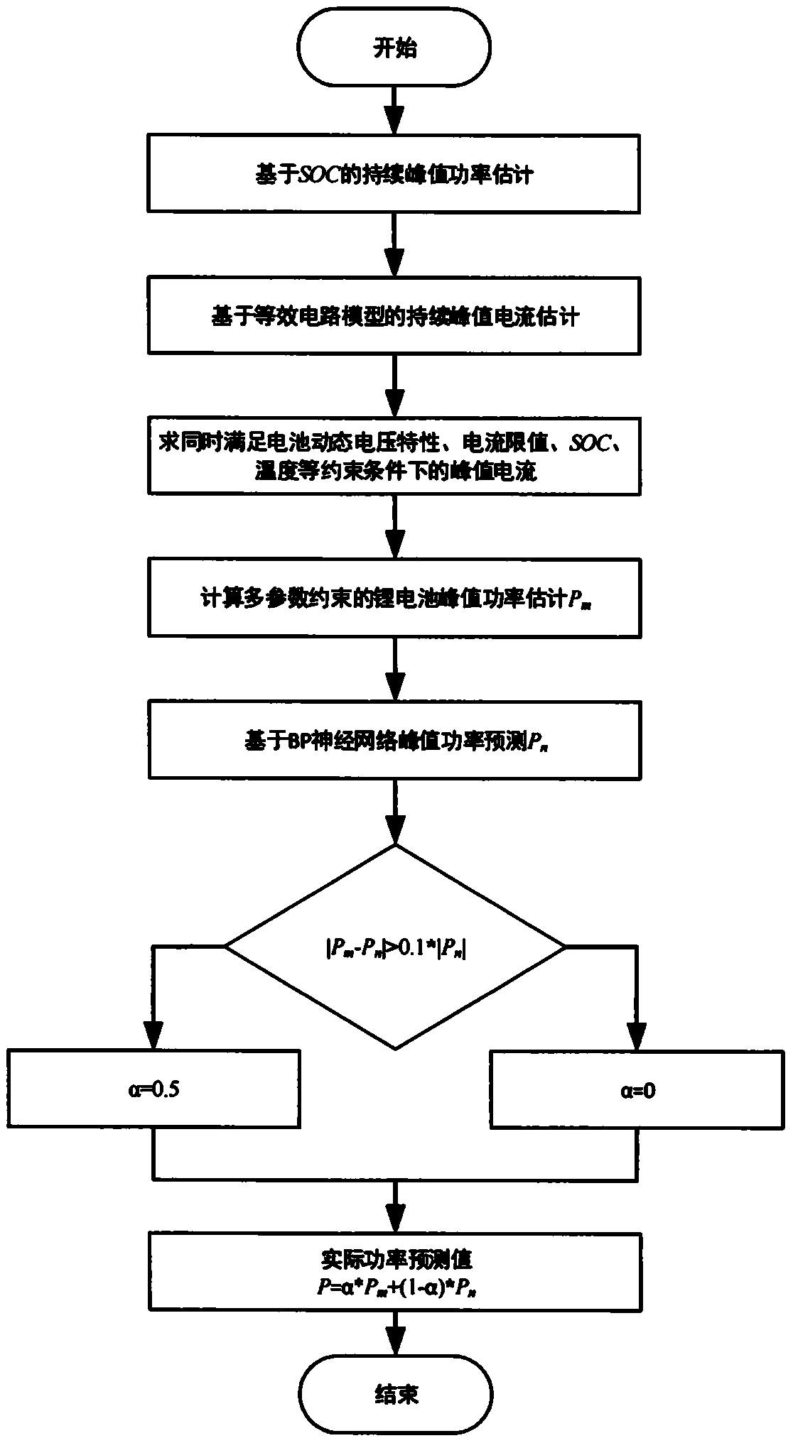
[0053] The present invention is further described below in conjunction with the accompanying drawings and specific embodiments: the present invention is a method for predicting dynamic peak power of a lithium battery, and its implementation steps are as follows.

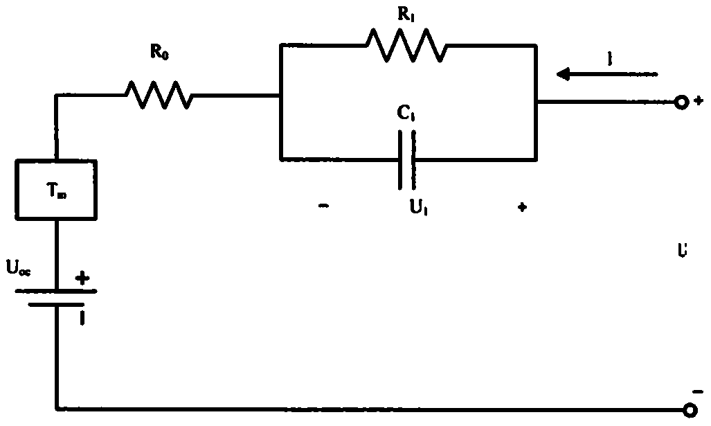
[0054] Step1: Collect basic data of lithium batteries, such as current, voltage, temperature, use HPPC (hybrid pulse power test) to identify the ohmic internal resistance R in the equivalent circuit model 0 , Polarization resistance R 1 and the polarizing capacitance C 1 , the capacity compensation is performed on the lithium battery equivalent circuit model, and the capacity expression of the lithium battery after capacity compensation is shown in formula (1).

[0055] Q(I,T,A)=C factor *f(I)*g(T)*Q N (20)

[0056] In the formula, Q(I, T, A) is the lithium battery capacity after compensation, Q N is the rated capacity of the lithium battery (at a specific discharge rate), f(I) is the influence factor of the ch...


PUM


Abstract

The invention relates to a lithium battery dynamic peak power prediction method. The method mainly comprises the following steps: firstly, carrying out SOC-based continuous peak current estimation andequivalent circuit model-based continuous peak current estimation; solving peak current simultaneously meeting the dynamic voltage characteristic, the current limit value, the SOC and the temperatureconstraint of the battery; and obtaining the lithium battery peak power prediction power Pm under the multi-parameter constraint, predicting the lithium battery peak power Pn by using a BP neural network, performing difference comparison on the Pm and the Pn, and performing weighting processing to obtain a final lithium battery peak power prediction result.

Description

technical field [0001] The invention relates to the field of battery management systems for electric vehicles, in particular to a method for predicting dynamic peak power of lithium batteries. Background technique [0002] In recent years, with the continuous growth of GDP and people's living standards, my country's automobile industry has developed rapidly. From January to October 2016, my country has achieved 22 million car sales, a year-on-year increase of 13.8%. The total annual car sales exceeded 27 million. There is no doubt that the auto industry has become the mainstay of national economic development. However, while the popularization and use of automobiles greatly facilitate people's lives, their exhaust emissions seriously threaten human health, causing air pollution, global warming and other issues. Compared with traditional fuel vehicles, electric vehicles use power batteries as the power source, basically do not emit harmful gases during driving, completely so...

Claims


Application Information

Patent Timeline
IPC IPC(8): G01R31/367B60L58/10
CPCY02T10/70
Inventor 朴昌浩易茂庆王平忠鱼苗陈涛
Owner CHONGQING UNIV OF POSTS & TELECOMM
Learn More