Device for burying and pressing drip irrigation tape on seeder
A drip irrigation belt and planter technology, which is applied in the directions of sowing planters, planter parts, watering devices, etc., can solve the problems of crop growth not reaching the expected effect, and achieve good growth effects.
- Summary
- Abstract
- Description
- Claims
- Application Information
AI Technical Summary
Problems solved by technology
Method used
Image
Examples
Embodiment 1
[0025] This embodiment provides a device for embedding a drip irrigation belt on a seeder, and realizes the present invention through the basic necessary technical features to solve the problems raised in the technical background section of this application document.
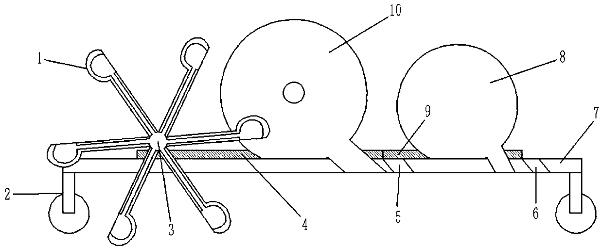
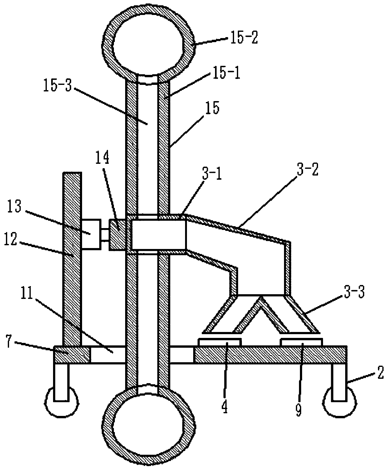
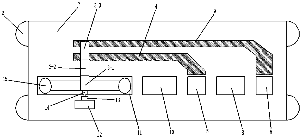
[0026] Specifically, such as Figure 1-3 As shown, the embodiment of the present invention provides a device for embedding drip irrigation belts on a planter, including a workbench 7, and a support wheel 2 is respectively provided on the left and right sides below the workbench 7, and the workbench 7 is arranged from left to right. The earth digging mechanism 1, the buried belt mechanism 10 for releasing the drip irrigation belt, the first excavation port 5, the seeding mechanism 8 for sowing seeds and the second excavation port 6 are arranged in sequence, the earth excavation mechanism 1, the buried tape mechanism 10, The first excavation port 5, the seeding mechanism 8 and the second excavation port 6 are loca...
Embodiment 2
[0029] This example is based on Example 1 and optimizes the implementation in Example 1, so that this example is more stable and has better performance during operation, but it is not limited to the one described in this example implementation.
[0030] Specifically, in this embodiment, the soil dividing mechanism 3 includes a soil collection cylinder 3-1 connected to the excavation end of the soil excavation mechanism 1, and the outlet end of the soil collection cylinder 3-1 is connected to the soil collection cylinder 3-1 through a connecting pipe 3-2. The soil-distributing pipe 3-3 is connected, and the soil-distributing pipe 3-3 has two excavation openings. The bottom of the connecting pipe 3-2 is fixed with a support rod, and the bottom of the support rod is fixed on the workbench 7.
[0031]The soil excavated by the excavating mechanism 1 enters the soil collecting cylinder 3-1 of the soil dividing mechanism 3, and when the soil in the soil collecting cylinder 3-1 is che...
Embodiment 3
[0038] This example is based on Example 1 and optimizes the implementation in Example 1, so that this example is more stable and has better performance during operation, but it is not limited to the one described in this example implementation.
[0039] Specifically, in this embodiment, the support wheel 2 on the right side of the workbench 7 is in the shape of a drum, and its length direction is consistent with the width direction of the workbench 7. The support wheel 2 on the right side of the workbench 7 is located at The right side of the second excavation port 6.
[0040] Using the drum-shaped supporting wheel 2 can make the soil on the seeds be compacted when the second excavation port 6 spreads the soil on the seeds, so that there is no need to use a separate manual or mechanical device to compact the soil. compaction, but along with the movement of the workbench 7, the soil is automatically compacted.
[0041] In this embodiment, the cross-sections of the first excav...
PUM
 Abstract
Description
Claims
Application Information
 - R&D
- Intellectual Property
- Life Sciences
- Materials
- Tech Scout
- Unparalleled Data Quality
- Higher Quality Content
- 60% Fewer Hallucinations
Browse by: Latest US Patents, China's latest patents, Technical Efficacy Thesaurus, Application Domain, Technology Topic, Popular Technical Reports.
© 2025 PatSnap. All rights reserved.Legal|Privacy policy|Modern Slavery Act Transparency Statement|Sitemap|About US| Contact US: help@patsnap.com


