Bamboo plywood shear wall

A bamboo plywood and shear wall technology, which is applied to walls, building components, buildings, etc., can solve the problems of low seismic performance of bamboo plywood shear walls, avoid nail pull-out damage, avoid board edge tearing, The effect of improving the shock resistance

Active Publication Date: 2020-07-03
NANJING FORESTRY UNIV
View PDF10 Cites 0 Cited by
  • Summary
  • Abstract
  • Description
  • Claims
  • Application Information

AI Technical Summary

Problems solved by technology

[0006] One of the objectives of the present invention is to overcome the problem that the stud columns of the bamboo plywood shear wall and the load-bearing members are not stably connected in the prior art so that the seismic performance of the bamboo plywood shear wall is not high, and to provide a bamboo plywood shear wall

Method used


Image

  • Bamboo plywood shear wall
  • Bamboo plywood shear wall
  • Bamboo plywood shear wall

Examples


Embodiment 1

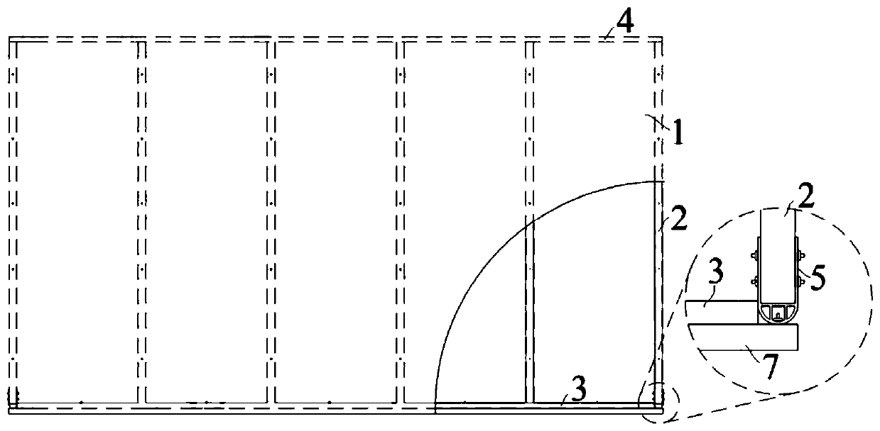
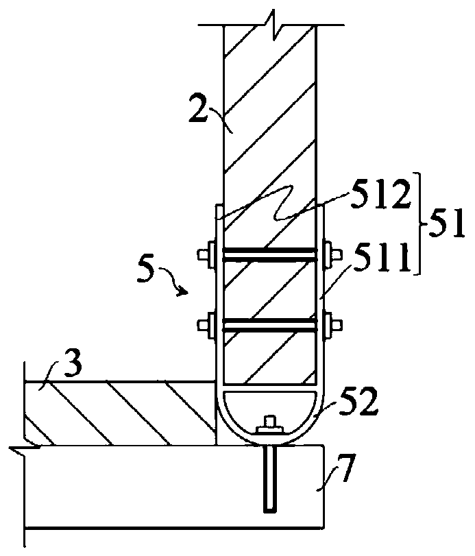
[0044] refer to figure 1, In this embodiment, the bamboo plywood shear wall includes a bottom beam plate 3 and a top beam plate 4 arranged parallel to each other, and a plurality of stud columns 2 are arranged between the bottom beam plate 3 and the top beam plate 4 . The studs 2 are parallel to each other, and the plurality of studs 2 specifically include the studs 2 at the ends near the two sides of the bottom beam plate 3, and the other studs 2 at the two ends. The stud column 2 on the inner side of the bottom beam plate 3 between.

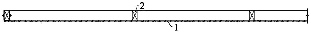
[0045] refer to figure 2 , There is also a bamboo plywood 1 between the bottom beam plate 3 and the top beam plate 4, and the bamboo plywood 1 is connected to the stud column 2. Specifically, the shape of the bamboo plywood 1 corresponds to the shape surrounded by the bottom beam 3, the top beam 4 and the stud column 2 at the end, that is, the upper and lower edges of the bamboo plywood 1 are in contact with the top beam 4 and the bottom. T...

Embodiment 2

[0055] refer to Figure 5 , in this embodiment, the bamboo plywood shear wall is also provided with two layers of gypsum boards 6 on both sides of the bamboo plywood 1, forming a bamboo plywood shear wall with a composite structure, thereby increasing the overall stability of the shear wall and beautify its appearance.

[0056] Specifically, refer to Figure 6 , the bottom beam board 3 and the top beam board 4 of the present embodiment are provided with two layers of gypsum boards 6, a layer of bamboo plywood 1 is arranged between the two layers of gypsum boards 6, and the two layers of gypsum boards 6 and the bamboo plywood 1 are arranged parallel to each other . A plurality of studs 2 are arranged in parallel between the gypsum board 6 and the bamboo plywood 1, and the positions of the studs 2 on both sides of the bamboo plywood 1 are corresponding, that is, the bamboo plywood 1 is sandwiched between two rows of studs 2 and are connected with two rows of stud columns 2, a...


PUM


Abstract

The invention discloses a bamboo plywood shear wall, and belongs to the technical field of building structures. The bamboo plywood shear wall comprises a bamboo plywood, a bottom beam plate and a topbeam plate, wherein a plurality of studs are arranged on one side of the bamboo plywood; the bamboo plywood covers the multiple studs and is connected onto the studs; the top ends of the studs are connected to the lower side surface of the top beam plate; the bottom ends of the studs are connected to the upper side surface of the bottom beam plate; the bottom end of the stud, on the end part, among the studs is provided with a connector; the connector is provided with a connecting part connected to the studs and an anchoring part back to the connecting part, and the anchoring part is providedwith a curved surface connected to a bearing component. While the bamboo plywood shear wall bears lateral force, an arc-shaped structure formed by the curved surface of the anchoring part allows the studs on the end part of the shear wall to freely rotate relative to the bearing component, so that bending moment, generated by eccentric pulling, on the studs on the end part is eliminated, and therefore, the stud on the end part is prevented from being broken and damaged, and lateral force resistance of a wall body is improved.

Description

technical field [0001] The invention relates to the technical field of building structures, in particular to a bamboo plywood shear wall. Background technique [0002] Compared with the wood-based structural panels commonly used in related fields, bamboo plywood is a structural panel with various sizes and specifications processed from bamboo using composite and recombination technologies. It has high strength, high rigidity, large format, Many advantages such as large-scale production. Therefore, the shear wall composed of bamboo plywood and wooden frame with excellent material properties can well avoid the unfavorable failure mode in the light wood shear wall, and is an efficient and high-performance lateral and load-bearing wall. It is conducive to achieving breakthroughs in the height and span of bamboo and wood structures. [0003] The Chinese patent document of the invention titled a bamboo-steel composite frame shear wall (application number 2018211856014) discloses...

Claims


Application Information

Patent Timeline
Patent Type & Authority Applications(China)
IPC IPC(8): E04B2/56E04B2/70E04B1/38
CPCE04B2/56E04B2/70E04B1/388
Inventor 郑维周宇李玥王弘历
Owner NANJING FORESTRY UNIV
Why Eureka
Try Eureka