
Experimental device and method of application of capillary tube with covering pressure

An experimental device and technology for thin tubes, which are used in earth-moving drilling, wellbore/well components, measurement, etc., can solve problems such as the limited lower limit of sand filling permeability in thin tubes, no consideration of overburden, and inability to consider sand cementation.

Active Publication Date: 2022-03-11
SOUTHWEST PETROLEUM UNIV +1
View PDF13 Cites 0 Cited by
  • Summary
  • Abstract
  • Description
  • Claims
  • Application Information

AI Technical Summary

Problems solved by technology

However, the existing thin tube method also has some defects. For example, the overburden pressure is not considered in the experimental process, and the lower limit of the permeability of sand filling in the narrow tube is limited. The sand can only be slowly filled into the thin tube without considering the cementation between sand particles, etc. The actual reservoir is quite different

Method used


Image

  • Experimental device and method of application of capillary tube with covering pressure
  • Experimental device and method of application of capillary tube with covering pressure
  • Experimental device and method of application of capillary tube with covering pressure

Examples


Embodiment Construction

[0032] The present invention will be further described below according to the accompanying drawings and examples, so that those skilled in the art can understand the present invention. However, it should be clear that the present invention is not limited to the scope of specific embodiments. For those of ordinary skill in the art, as long as various changes are within the spirit and scope of the present invention defined and determined by the appended claims, they are all within the scope of protection. List.

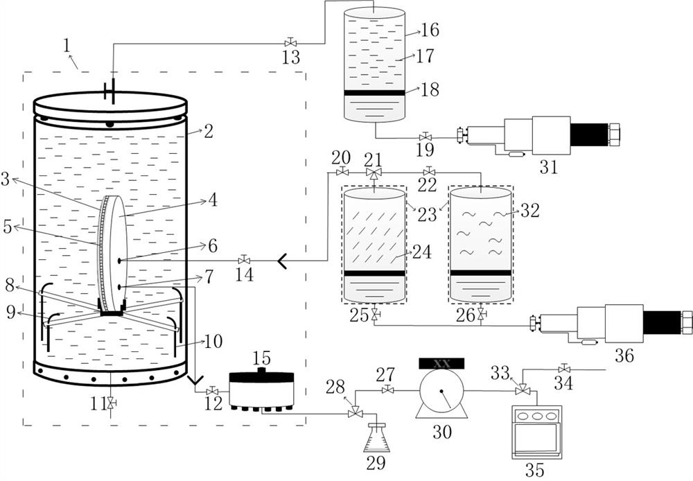
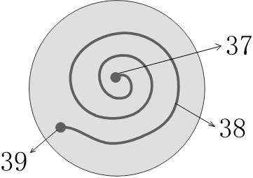
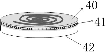
[0033] see figure 1 , figure 2 , Figure 4 .

[0034] A capillary experimental device with pressure covering is composed of a high and low temperature test chamber 1, an autoclave 2, a capillary column 4, a rubber sheath 3, a fluid injection system and a fluid extraction system.

[0035] The autoclave 2 is placed in the high and low temperature test chamber 1, and the autoclave is connected with an intermediate container 16 and a displacement pump 31, and there are...


PUM


Abstract

The invention relates to a capillary experimental device with pressure, which is composed of a high and low temperature test chamber, an autoclave, a capillary column, a rubber sleeve, a fluid injection system and a fluid extraction system, and the upper surface of the capillary column is engraved with a spiral groove , the two ends of the groove are respectively connected to the fluid injection and extraction systems through vertical circular holes. The method for using the device to determine the miscible pressure of injected gas and crude oil includes: filling sand in the groove and round hole of the narrow pipe column; injecting hydraulic oil into the autoclave, and injecting nitrogen into the sand filled in the groove of the thin pipe column; The prepared formation crude oil is used to displace the nitrogen in the groove of the thin pipe column; the injected gas displaces the crude oil in the groove of the thin pipe column at a certain speed; the oil recovery rate R is taken as the ordinate, and the pressure P is taken as the abscissa, Draw the relationship curve between R and P, and the pressure point corresponding to the oil recovery rate of 90% is the miscible pressure of the injected gas and crude oil. The invention is reliable in principle and easy to operate, and can provide technical support for the scheme design of the actual gas injection and oil production process.

Description

technical field [0001] The invention belongs to the field of oil and gas development, and relates to an experimental device and a use method of a capillary tube covered with pressure. Background technique [0002] Crude oil mainly occurs in rock pores, and the recovery rate is not high by conventional depressurization mining methods. Especially for low-permeability and ultra-low-permeability reservoirs, the conventional recovery rate is not only low due to the small diameter of core pore throats, but also The chemical agent method cannot be implemented, and gas injection oil recovery is currently the main enhanced oil recovery technology. Gas injection flooding includes two types: miscible flooding and immiscible flooding. The main difference between the two methods is whether the injected gas front and oil are miscible during the displacement process. Theoretically, the efficiency of gas injection miscible flooding can reach 100%, which is much higher. in immiscible drive....

Claims


Application Information

Patent Timeline
Patent Type & Authority Patents(China)
IPC IPC(8): E21B49/00E21B47/00E21B43/16
CPCE21B49/00E21B47/00E21B43/168
Inventor 刘煌李瑞景杨志鹏詹思源郭平汪周华杜建芬代潘祥
Owner SOUTHWEST PETROLEUM UNIV
Learn More