Combustion cavity structure of environment-friendly combustible waste heat recovery device

A heat recovery device and waste technology, applied in the combustion method, combustion type, combustion technology mitigation and other directions, can solve the problem of low waste heat recovery efficiency, and achieve the effect of full utilization and high heating efficiency

Inactive Publication Date: 2020-07-03
北京百年初心科技有限公司
View PDF0 Cites 2 Cited by
  • Summary
  • Abstract
  • Description
  • Claims
  • Application Information

AI Technical Summary

Problems solved by technology

[0003] Aiming at the above problems, the present invention discloses a combustion chamber structure of an environment-friendly combustible waste heat recovery device to solve the problem of low waste heat recovery efficiency in the prior art

Method used


Image

  • Combustion cavity structure of environment-friendly combustible waste heat recovery device
  • Combustion cavity structure of environment-friendly combustible waste heat recovery device
  • Combustion cavity structure of environment-friendly combustible waste heat recovery device

Examples


Embodiment Construction

[0020] In order to make the technical solution of the present invention clearer, the present invention will be further described below in conjunction with the accompanying drawings. Any solution obtained by equivalent replacement and conventional reasoning of the technical features of the technical solution of the present invention falls within the protection scope of the present invention. The fixed connection mentioned in the present invention and the fixed arrangement are common connection methods in the mechanical field, and welding, bolt and nut connection and screw connection are all available.

[0021] In describing the present invention, it is to be understood that the terms "upper", "lower", "front", "rear", "left", "right", "vertical", "horizontal", "top" , "bottom", "inner", "outer" and other indicated orientations or positional relationships are based on the orientations or positional relationships shown in the drawings, and are only for the convenience of describin...


PUM


Abstract

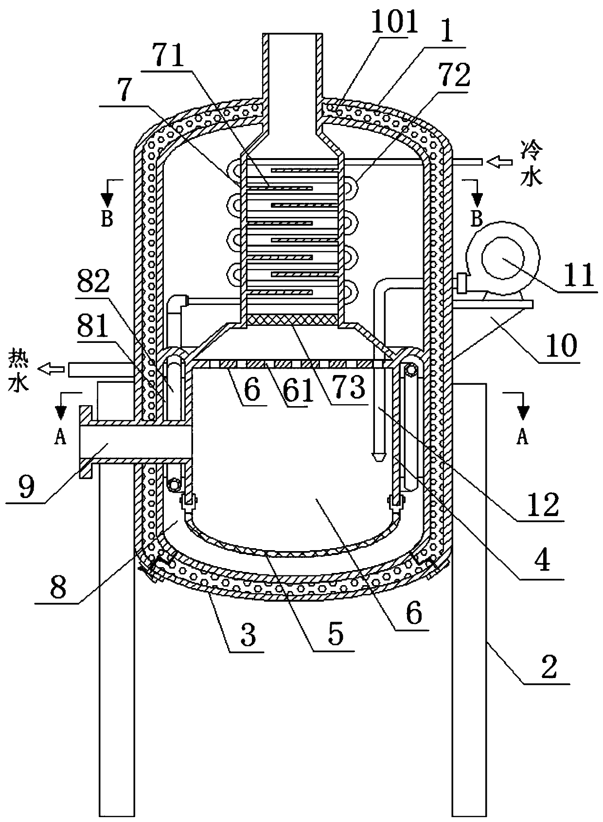
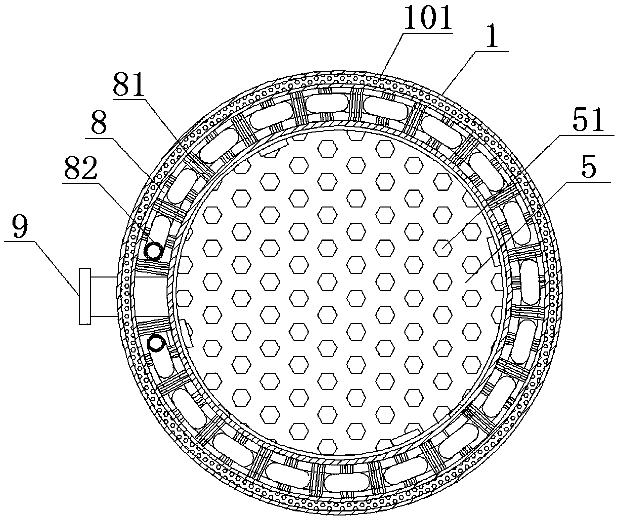
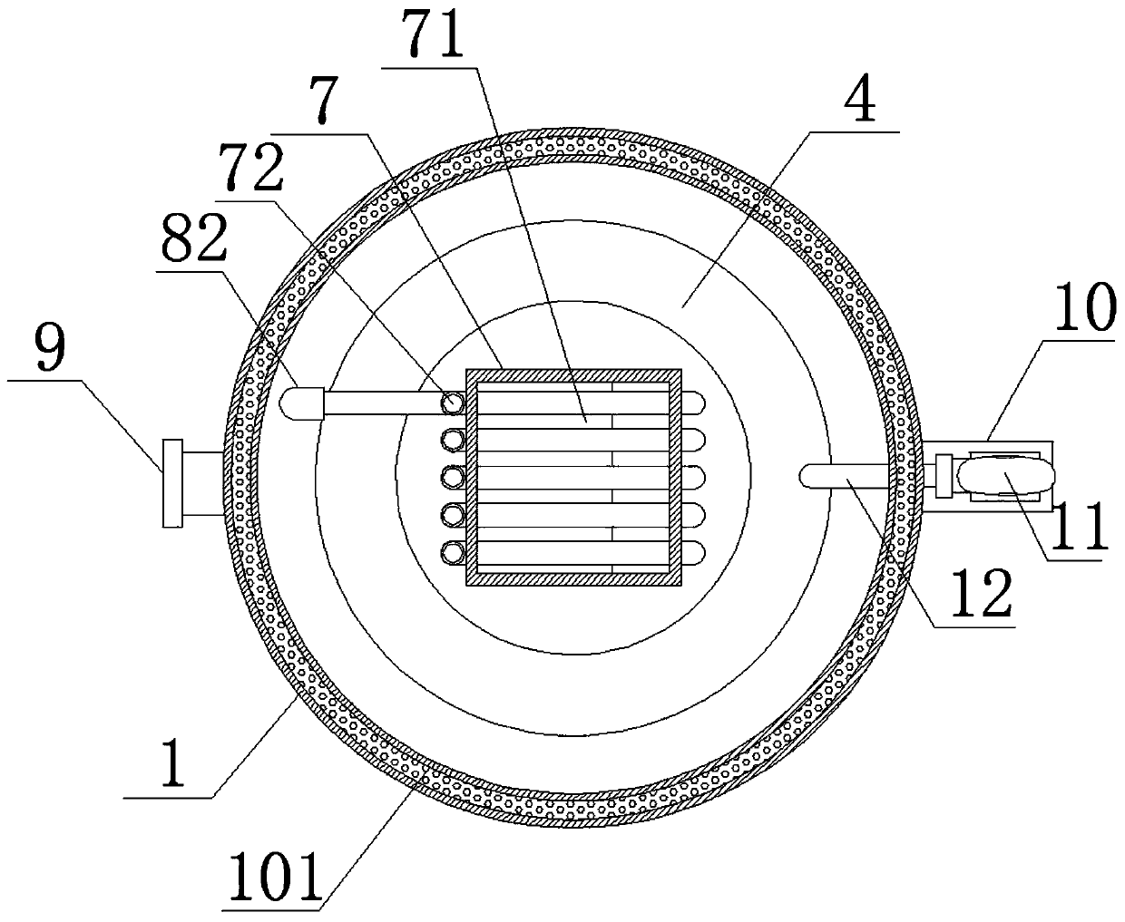
The invention relates to a combustion cavity structure of an environment-friendly combustible waste heat recovery device. The combustion cavity structure comprises a combustion furnace shell, a combustion liner is arranged inside the combustion furnace shell, the upper end of the combustion liner is fixedly connected with the inner wall of the middle of the combustion furnace shell, a heat conduction cavity is formed between the combustion liner and the combustion furnace shell, and a plurality of metal heat conduction plates are longitudinally arranged in the heat conduction cavity. The plurality of metal heat conduction plates are arranged between the combustion liner and the combustion furnace shell in a circular shape, the two sides of the metal heat conduction plate are connected withthe combustion liner and the combustion furnace shell correspondingly, a second heat conduction pipe is coiled on the metal heat conduction plate, one end of the second heat conduction pipe penetrates through the side wall of the combustion furnace shell and is connected with a hot water receiving end, and the other end of the second heat conduction pipe extends upwards and penetrates through thecombustion liner and is connected with the first heat conduction pipe. The heating efficiency is high, the water temperature can reach higher temperature, and the requirement for high-temperature hotwater supply is met.

Description

technical field [0001] The invention belongs to the technical field of heat recovery devices, and in particular relates to a combustion cavity structure of an environment-friendly combustible waste heat recovery device. Background technique [0002] With the increasing tension of energy forms, there is still a phenomenon of energy waste, especially in industrial production, which will generate a large amount of waste heat, and these waste heat resources can be recycled and reused, which can effectively alleviate the tension of energy forms. The high-temperature waste generated in the industry itself contains a lot of heat and is not convenient for direct treatment. By burning it and recovering the high temperature generated, it can be effectively recycled and processed, which can meet the requirements of energy conservation and environmental protection. The waste heat recovery device uses a heat exchanger as the main component to transfer the excess heat generated by one dev...

Claims


Application Information

Patent Timeline
IPC IPC(8): F23G5/24F23G5/44F23G5/46F23J15/06
CPCF23G5/24F23G5/44F23G5/46F23J15/06Y02E20/30
Inventor 崔建中
Owner 北京百年初心科技有限公司
Why Eureka
Try Eureka