Novel vacuum drying tunnel furnace body structure and tunnel type vacuum drying system

A technology of vacuum drying and furnace structure, which is applied in the direction of drying solid materials, drying gas arrangement, and drying solid materials without heating. It can solve the problems of inconvenient maintenance, inconvenient installation, and pollution of dry items, etc., and achieves convenient installation and maintenance. , the effect of saving manpower and material resources

Pending Publication Date: 2020-07-03
SHENZHEN TIME HIGH TECH EQUIP
View PDF0 Cites 1 Cited by
  • Summary
  • Abstract
  • Description
  • Claims
  • Application Information

AI Technical Summary

Problems solved by technology

[0003] In order to overcome the deficiencies in the prior art, one of the purposes of the present invention is to disclose a novel vacuum drying tunnel furnace body structure to solve the problems of inconvenient installation, inconvenient maintenance and pollution drying in the existing novel vacuum drying tunnel furnace body structure. item problem

Method used


Image

  • Novel vacuum drying tunnel furnace body structure and tunnel type vacuum drying system
  • Novel vacuum drying tunnel furnace body structure and tunnel type vacuum drying system
  • Novel vacuum drying tunnel furnace body structure and tunnel type vacuum drying system

Examples


Embodiment Construction

[0030] Below, the present invention will be further described in conjunction with the accompanying drawings and specific implementation methods. It should be noted that, under the premise of not conflicting, the various embodiments described below or the technical features can be combined arbitrarily to form new embodiments. .

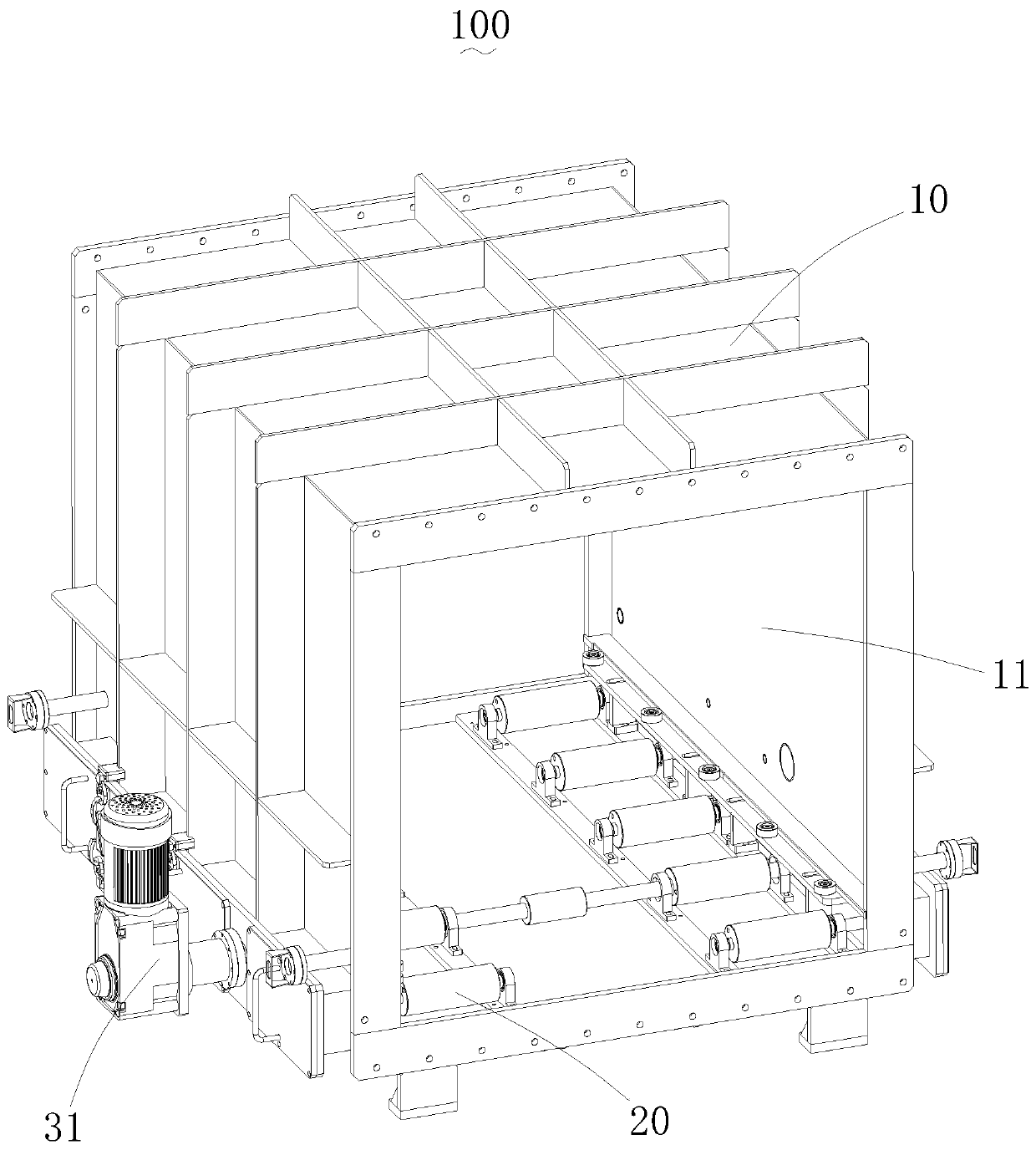
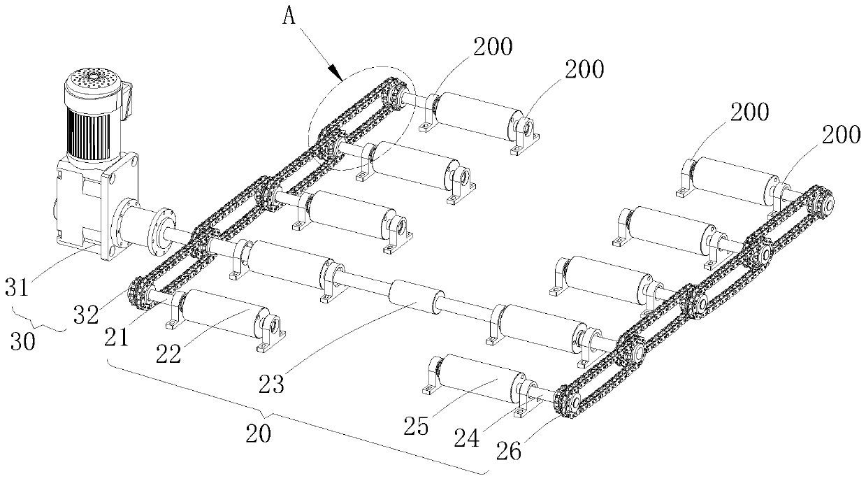
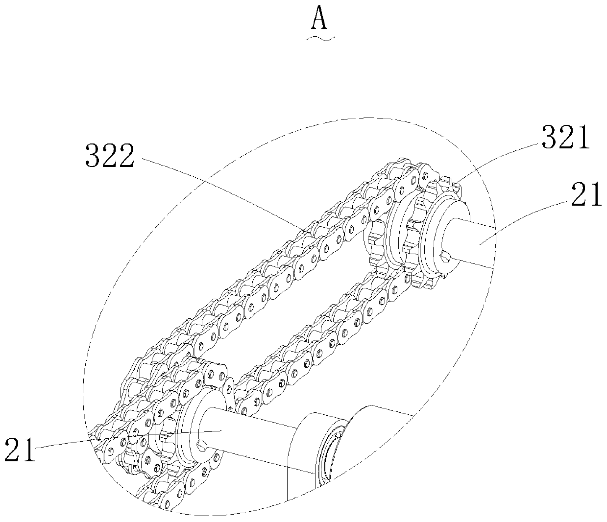
[0031] see Figure 1-7 , a new type of vacuum drying tunnel furnace body structure 100 disclosed in the embodiment of the present invention, including a furnace body 10, a roller conveying mechanism 20 and a driving mechanism 30, the furnace body 10 has a drying chamber 11, and the roller conveying mechanism 20 is used for drying in the drying chamber 11 for conveying items, the roller conveying mechanism 20 is rotatably mounted on the furnace body 10 , the driving mechanism 30 is used to drive the roller conveying mechanism 20 to rotate, and the driving mechanism 30 is arranged on the outer wall of the furnace body 10 .

[0032] When in use, the driv...


PUM


Abstract

The invention discloses a novel vacuum drying tunnel furnace body structure and a tunnel type vacuum drying system. The novel vacuum drying tunnel furnace body structure comprises a furnace body, a roller conveying mechanism and a driving mechanism, wherein the furnace body is provided with a drying cavity; the roller conveying mechanism is used for conveying articles in the drying cavity, and theroller conveying mechanism is rotatably mounted on the furnace body; and the driving mechanism is used for driving the roller conveying mechanism to rotate, and the driving mechanism is arranged on the outer side wall of the furnace body. The novel vacuum drying tunnel furnace body structure has the following advantages that mounting is convenient, and mounting personnel do not need to enter thedrying cavity for mounting; on-site maintenance is convenient, when the driving mechanism goes wrong, maintenance personnel can maintain and replace parts of the driving mechanism on the outer side wall of the furnace body without entering the drying cavity, so that the operation of cleaning the articles in the drying cavity before maintenance is avoided, and manpower and material resources are saved; and metal dust generated by abrasion during operation of the driving mechanism cannot pollute the articles in the drying cavity.

Description

technical field [0001] The invention relates to the drying field, in particular to a novel vacuum drying tunnel furnace body structure and a tunnel-type vacuum drying system adopting the novel vacuum drying tunnel furnace body structure. Background technique [0002] In the lithium battery production process, in order to remove the moisture in the battery, vacuum drying is an essential step. Tunnel vacuum drying is a way with higher drying efficiency. In the tunnel-type vacuum drying oven, the transmission chain will be arranged evenly and orderly, and the batteries in the tray will be sent into the drying oven to be heated and dried to remove the moisture in the batteries. In the current tunnel-type vacuum drying furnace, the transmission chain is located inside the drying furnace cavity, which brings a lot of inconvenience: 1) It is inconvenient to install, and the installer needs to enter the cavity to install; 2) It is inconvenient to maintain on site, the chain is brok...

Claims


Application Information

Patent Timeline
Patent Type & Authority Applications(China)
IPC IPC(8): F27B9/02F27B9/04F27B9/12F27B9/24F26B5/04F26B5/06F26B15/14F26B21/04F26B23/06F26B25/06F25D3/11
CPCF25D3/11F26B5/04F26B5/06F26B15/14F26B21/001F26B21/004F26B21/04F26B23/06F26B25/06F27B9/02F27B9/042F27B9/12F27B9/24F27B2009/122F27B2009/124
Inventor 田汉溶杨毅丁笑王斌全
Owner SHENZHEN TIME HIGH TECH EQUIP
Why Eureka
Try Eureka