Battery three-dimensional interlayer diaphragm structure with graded liquid retention capacity
A diaphragm structure and interlayer technology, which is applied in the field of battery three-dimensional interlayer diaphragm structure, can solve problems such as affecting battery safety performance, affecting battery rate performance, and reducing the amount of electrolyte, preventing battery safety and electrical performance problems, and having great practical significance in production. , The effect of structural design science
- Summary
- Abstract
- Description
- Claims
- Application Information
AI Technical Summary
Problems solved by technology
Method used
Image

Examples
Embodiment Construction
[0024] In order to enable those skilled in the art to better understand the solution of the present invention, the present invention will be further described in detail below in conjunction with the accompanying drawings and embodiments.
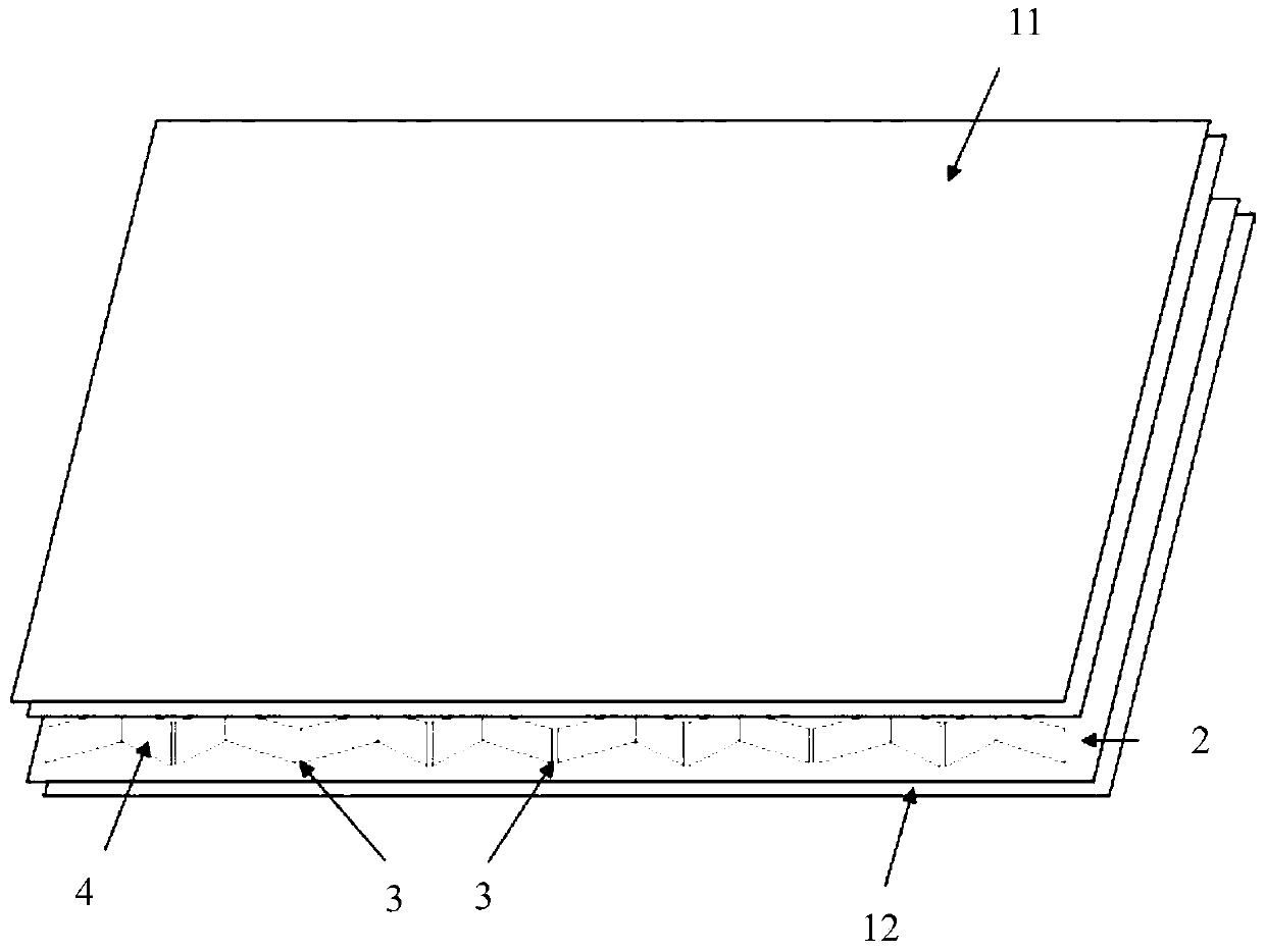
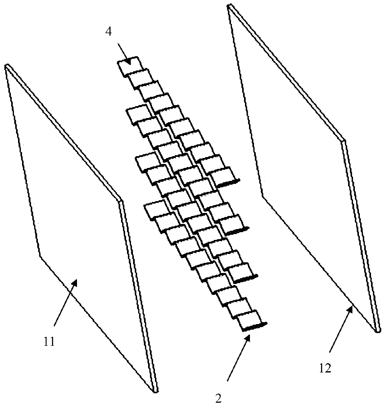
[0025] see Figure 1 to Figure 4 , the present invention provides a battery three-dimensional sandwich diaphragm structure with graded liquid retention capacity, comprising a front surface layer base film 11 and a rear surface layer base film 12 distributed at intervals;
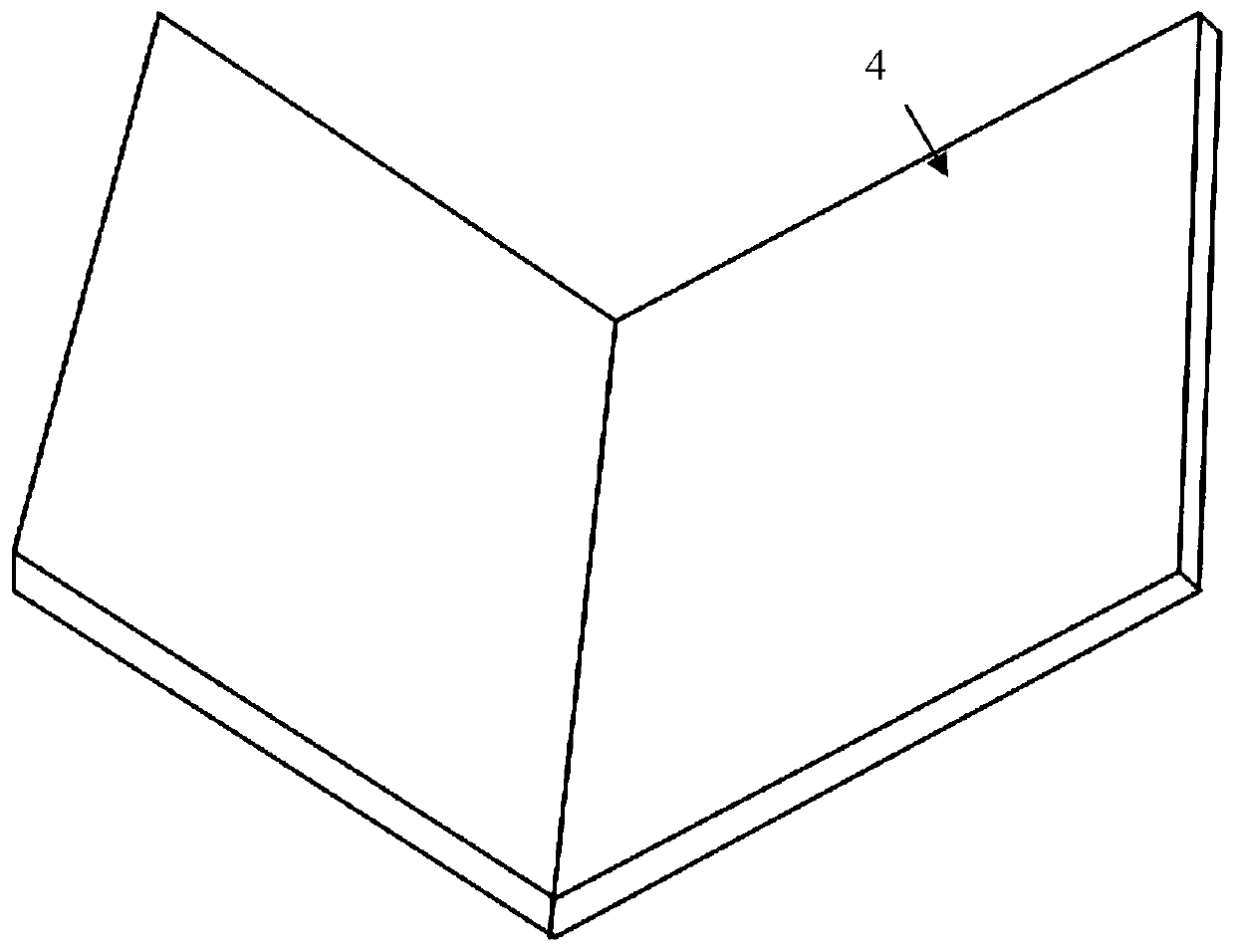
[0026] In the cavity between the base film 11 of the front surface layer and the base film 12 of the back surface layer, a plurality of laterally distributed liquid storage interlayers 2 are sequentially arranged at intervals from top to bottom;
[0027] The liquid storage interlayer 2 is used to separate the cavity between the front surface layer basement film 11 and the rear surface layer basement film 12 into a plurality of independent liquid storage channels (that is, ...
PUM
| Property | Measurement | Unit |
|---|---|---|
| Thickness | aaaaa | aaaaa |
Abstract
Description
Claims
Application Information
 - R&D
- Intellectual Property
- Life Sciences
- Materials
- Tech Scout
- Unparalleled Data Quality
- Higher Quality Content
- 60% Fewer Hallucinations
Browse by: Latest US Patents, China's latest patents, Technical Efficacy Thesaurus, Application Domain, Technology Topic, Popular Technical Reports.
© 2025 PatSnap. All rights reserved.Legal|Privacy policy|Modern Slavery Act Transparency Statement|Sitemap|About US| Contact US: help@patsnap.com