High-Q-value miniaturized dielectric waveguide filter
A dielectric waveguide and filter technology, which is applied in the field of communication accessories, can solve the problems that metal filters cannot meet the miniaturization and low cost requirements of 5G communication systems, and the limitations of communication technology development, so as to reduce size, reduce frequency, and improve Q value effect
- Summary
- Abstract
- Description
- Claims
- Application Information
AI Technical Summary
Problems solved by technology
Method used
Image

Examples
Embodiment 1
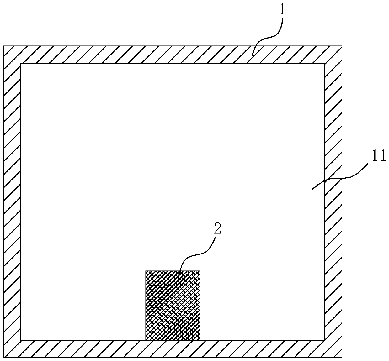
[0022] A high-Q miniaturized dielectric waveguide filter, such as figure 1 As shown, it includes: a shielding box 1 made of a material with a first dielectric constant, and a shielding cavity 11 is formed in the shielding box 1; The frequency-reducing component 2 produced has a second dielectric constant greater than the first dielectric constant. Specifically, the second dielectric constant is usually 1.5-2.5 times the first dielectric constant. In this embodiment, the second dielectric constant is is twice the first dielectric constant, the size, shape and position of the frequency reduction component 2 can be adjusted according to actual needs, such as the shape of the frequency reduction component 2 is not limited to a cylinder, and can be designed into any shape according to the actual process production requirements , and the down-frequency component 2 can be produced as a standard part, which provides greater convenience for subsequent product design and development.
...
Embodiment 2
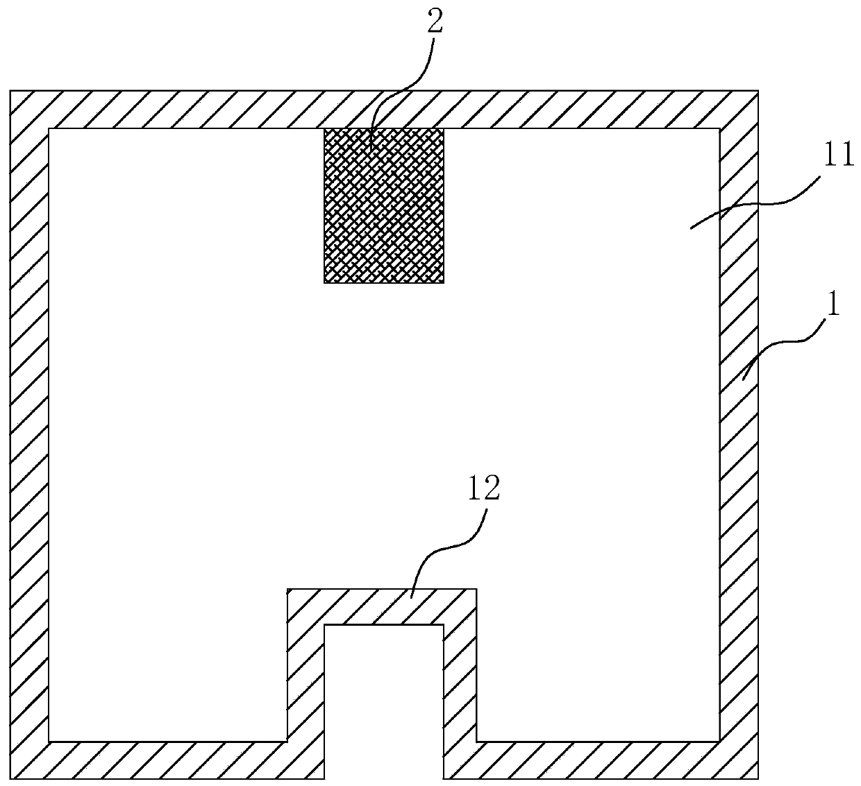
[0025] The difference between this embodiment and Embodiment 1 is: in this embodiment, if figure 2 As shown, the shielding box 1 is also provided with an inwardly recessed loading protrusion 12. By setting the loading protrusion 12, the frequency can be further reduced. Play 12 opposite sides.
Embodiment 3
[0027] This embodiment is described with a specific scheme: the first dielectric constant is 20, the second dielectric constant is 40, the size of the shielding box 1 is 10mmx10mmx6mm, the frequency can reach 4.2GHz at this time, and the Q value is about 1900; The existing shielding cavity 11 made of a single dielectric constant material can only make the frequency reach 4.2 GHz and the Q value reach 1600 on the basis of setting the loading protrusion 12. If the loading protrusion 12 is not provided, the shielding cavity needs to be greatly increased. The size of the cavity 11 can make the frequency reach 4.2GHz and the Q value reach 1900; it can be seen that by setting the frequency reduction component 2, the size of the shielding box 1 can be effectively reduced, and the Q value is increased at the same time, and the filter performance is improved. The breadth of application.
PUM
| Property | Measurement | Unit |
|---|---|---|
| size | aaaaa | aaaaa |
| q value | aaaaa | aaaaa |
Abstract
Description
Claims
Application Information
 - R&D
- Intellectual Property
- Life Sciences
- Materials
- Tech Scout
- Unparalleled Data Quality
- Higher Quality Content
- 60% Fewer Hallucinations
Browse by: Latest US Patents, China's latest patents, Technical Efficacy Thesaurus, Application Domain, Technology Topic, Popular Technical Reports.
© 2025 PatSnap. All rights reserved.Legal|Privacy policy|Modern Slavery Act Transparency Statement|Sitemap|About US| Contact US: help@patsnap.com