Compensation method for position estimation of permanent magnet linear motor rotor by high-frequency injection method

A permanent magnet linear motor and mover position technology, which is used in the control of electromechanical transmissions, control of generators, electronic commutators, etc.

Active Publication Date: 2020-07-03
JINCHENG COLLEGE NANJING UNIV OF AERONAUTICS & ASTRONAUTICS
View PDF6 Cites 2 Cited by
  • Summary
  • Abstract
  • Description
  • Claims
  • Application Information

AI Technical Summary

Problems solved by technology

[0006] The position sensorless compensation algorithms of these rotating motors can be transplanted to the position sensorless control of permanent magnet linear motors to compensate the position estimation error, b

Method used


Image

  • Compensation method for position estimation of permanent magnet linear motor rotor by high-frequency injection method
  • Compensation method for position estimation of permanent magnet linear motor rotor by high-frequency injection method
  • Compensation method for position estimation of permanent magnet linear motor rotor by high-frequency injection method

Examples


Embodiment Construction

[0051] The technical solutions and beneficial effects of the present invention will be described in detail below in conjunction with the accompanying drawings.

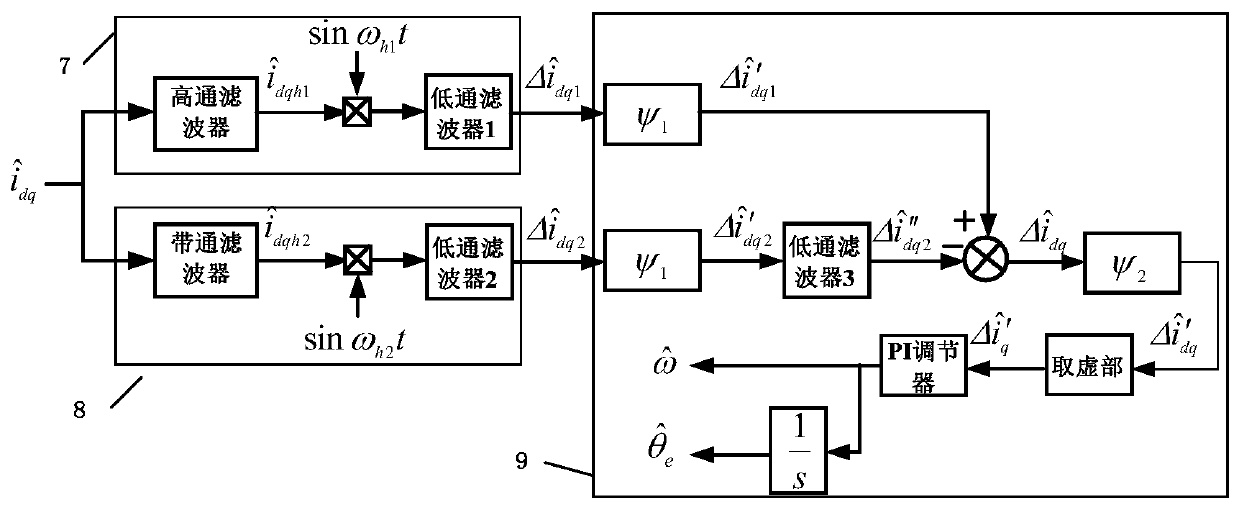
[0052] The present invention provides a compensation method for the estimation of the position of the mover of the permanent magnet linear motor by the high-frequency injection method, which functionally includes three units, such as image 3 As shown, they are respectively the first high-frequency injection unit 7, the second high-frequency injection unit 8, and the position estimation error compensation unit 9. The specific content of the compensation method is: the first current signal is obtained through the first high-frequency injection unit, The second current signal is obtained through the second high-frequency injection unit, and two compensation vectors are designed according to the position estimation error information contained in the first current signal and the second current signal, which are respectivel...


PUM


Abstract

The invention discloses a compensation method for position estimation of a rotor of a permanent magnet linear motor by a high-frequency injection method, which comprises the following steps of: filtering a current response signal to obtain a first current signal and a second current signal, and designing a first compensation vector and a second compensation vector according to included position estimation error information; multiplying the first compensation vector by the first current signal and the second current signal respectively to obtain a first current vector and a second current vector; carrying out low-pass filtering on the second current vector, subtracting the second current vector from the first current vector, and multiplying the second current vector by the second compensation vector to obtain a second current difference vector; sending the imaginary part of the second current difference vector to a PI regulator for integration to obtain a mover estimation position; andtaking the mover angular frequency estimated value and the mover position estimated value as feedback signals, and controlling the difference between the actual position of the motor mover and the mover estimated position to converge to zero, so that the motor operates stably. The method can obviously inhibit the position estimation error caused by the end effect, effectively improves the precision of estimating the position of the linear motor rotor by adopting a high-frequency injection method, and is simple and easy to implement.

Description

technical field [0001] The invention belongs to the field of linear motors, in particular to a compensation method for estimating the position of a mover of a permanent magnet linear motor with a high-frequency injection method. Background technique [0002] With the development of industrial applications, linear motors are widely used in production lines, intelligent elevators, maglev trains, and other high-speed, high-precision control devices. In the case of linear drive, compared with rotary motors, linear motors have simple structure, small inertia, fast response speed, can directly generate linear thrust, high efficiency and low construction cost. [0003] In order to realize the high-performance linear motor control, it is necessary to obtain the position and speed information of the linear motor. If you refer to the installation method of the speed sensor of the rotating motor, the speed sensor of the linear motor needs to lay a grating scale along the linear track ...

Claims


Application Information

Patent Timeline
IPC IPC(8): H02P21/18H02P21/22H02P25/064H02P6/18
CPCH02P6/183H02P21/18H02P21/22H02P25/064
Inventor 郝雯娟王宇
Owner JINCHENG COLLEGE NANJING UNIV OF AERONAUTICS & ASTRONAUTICS
Why Eureka
Try Eureka