Rubbish barrel capable of separating rubbish bag

A garbage bag and garbage can technology, applied in the field of garbage cans, can solve problems such as trouble, loss of use value of wet garbage, and addition of fertilizer production process

Pending Publication Date: 2020-07-07
孙新宇
View PDF0 Cites 3 Cited by
  • Summary
  • Abstract
  • Description
  • Claims
  • Application Information

AI Technical Summary

Problems solved by technology

Kitchen waste is an excellent raw material for making pollution-free organic fertilizers, but if various plastic bags are

Method used


Image

  • Rubbish barrel capable of separating rubbish bag
  • Rubbish barrel capable of separating rubbish bag
  • Rubbish barrel capable of separating rubbish bag

Examples


Example Embodiment

[0034] Example one:

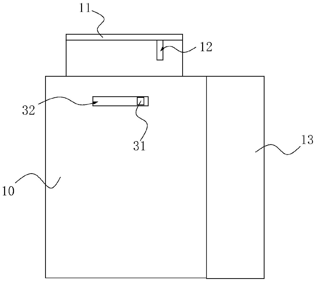
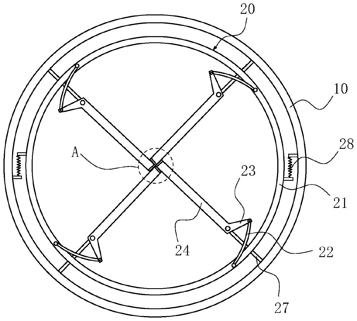
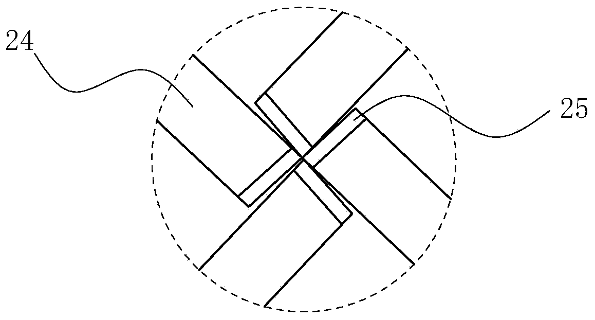
[0035] Such as figure 1 , figure 2 with image 3 As shown together, a trash can with a separable garbage bag includes a barrel body 10, the top of the barrel body 10 is provided with a discharge port, a bag cutting device 20 is provided in the barrel body 10, and the bag cutting device 20 is located below the discharge port. The bag cutting device 20 is connected with a driving mechanism for driving the bag cutting device 20 to move. The bag cutting device 20 includes a ring frame 21 connected with a driving mechanism and four swing arms that are evenly hinged on the ring frame 21. The end of the swing arm at the center of the ring frame 21 is equipped with a blade 25. The driving mechanism drives the ring frame 21 to rotate. , The swing arm drives the blade 25 to move away from the center position of the ring frame 21. The first swing arm 23, the second swing arm 24 and the blade 25 are all correspondingly arranged in four, which can be cut into a cross-s...

Example Embodiment

[0044] Embodiment two:

[0045] This implementation mode is basically the same as the solution of Example 1, and the difference lies in:

[0046] Such as Image 6 As shown, the driving mechanism includes a motor 33. The output end of the motor 33 is connected with a gear 34 for transmission. The outer edge of the ring frame 21 is provided with external teeth that can mesh with the gear 34. The switch of the driving motor 33 can be arranged on the outside of the barrel 10. The bag cutting device 20 can be driven by pressing the switch to drive the motor 33 to cut the garbage bag.

Example Embodiment

[0047] Embodiment three:

[0048] This implementation mode is basically the same as the solution of Example 1, and the difference lies in:

[0049] Such as Figure 7 As shown, the driving mechanism includes a first pedal 35 and a first connecting rod 36 hinged to the first pedal 35. A first fulcrum 37 is fixed at the bottom of the barrel 10, and the first pedal 35 is hinged on the first fulcrum 37. A connecting member 38 is sleeved on the first connecting rod 36, and the inner side of the connecting member 38 is provided with internal threads to connect with the first connecting rod 36, and the outer side of the connecting member 38 is provided with gear teeth and external teeth provided on the outer edge of the ring frame 21 In the engagement, by stepping on the first step rod 35 to expose one end of the barrel body 10, the first connecting rod 36 can be moved upward, so that the connecting member 38 rotates to drive the ring frame 21 to rotate. Wherein, the barrel body 10 cannot...


PUM


Abstract

The invention discloses a rubbish barrel capable of separating a rubbish bag and belongs to the technical field of rubbish barrels. The rubbish barrel comprises a barrel body, the top of the barrel body is provided with an input mouth, the rubbish barrel is characterized in that the barrel body is internally provided with a bag cutting device, the bag cutting device is located below the input mouth, is connected with a driving mechanism used for driving the bag cutting device to act and comprises an annular rack connected with the driving mechanism and four swing arms evenly hinged to the annular rack, the ends, located at the central position of the annular rack, of the swing arms are provided with cutter blades, and when the driving mechanism drives the annular rack to rotate, the cutterblades move to the direction away from the central position of the annular rack. According to the rubbish barrel capable of separating the rubbish bag, the bag cutting device can cut the bottom of the rubbish bag into a cross opening, so that rubbish and the rubbish bag are separated in the case of not dirtying hands, and the rubbish barrel is convenient to use.

Description

Technical field [0001] The invention belongs to the technical field of trash cans, and specifically relates to a trash can with a separable garbage bag. Background technique [0002] Garbage is a resource that has been misplaced. As long as it is sorted, most of the garbage can be recycled and reused. The country has begun to gradually promote garbage sorting. However, after the garbage is sorted, it is necessary to put the garbage bag to the garbage bin for disposal. How to separate the wet garbage, which is mainly kitchen waste, from the garbage bag without dirtying your hands becomes a big problem. problem. Kitchen waste is an excellent raw material for the production of pollution-free organic fertilizers, but if it is mixed with various plastic bags, it will add great trouble to the fertilizer production process, and even make the wet waste lose its use value. Summary of the invention [0003] The technical problem to be solved by the present invention is to provide a trash ...

Claims


Application Information

Patent Timeline
IPC IPC(8): B65F1/14B65F1/08B65F1/00B65F1/06B65B69/00
CPCB65B69/0008B65F1/0033B65F1/062B65F1/08B65F1/14B65F2210/126B65F2210/176Y02W30/10
Inventor 孙新宇
Owner 孙新宇
Why Eureka
Try Eureka