Clean incinerator

An incinerator and clean technology, applied in the direction of incinerator, combustion method, combustion type, etc., can solve the problems of large environmental pollution, low combustion efficiency, and high content of harmful gases

Active Publication Date: 2020-07-07
ZHEJIANG SANLIAN ENVIRONMENT MACHINERY EQUIP
View PDF6 Cites 5 Cited by
  • Summary
  • Abstract
  • Description
  • Claims
  • Application Information

AI Technical Summary

Problems solved by technology

[0005] The purpose of the present invention is to solve the problem that the existing incinerator has low combustion efficiency, the harmful gas in the tail gas is difficult to be fully combusted and decomposed, resulting in a high content of harmful gas in the tail gas, which causes great pollution to the environment, and provides a combustion efficiency High clean incinerator can effectively decompose harmful gases in the tail gas and reduce environmental pollution

Method used


Image

  • Clean incinerator
  • Clean incinerator
  • Clean incinerator

Examples


Embodiment 1

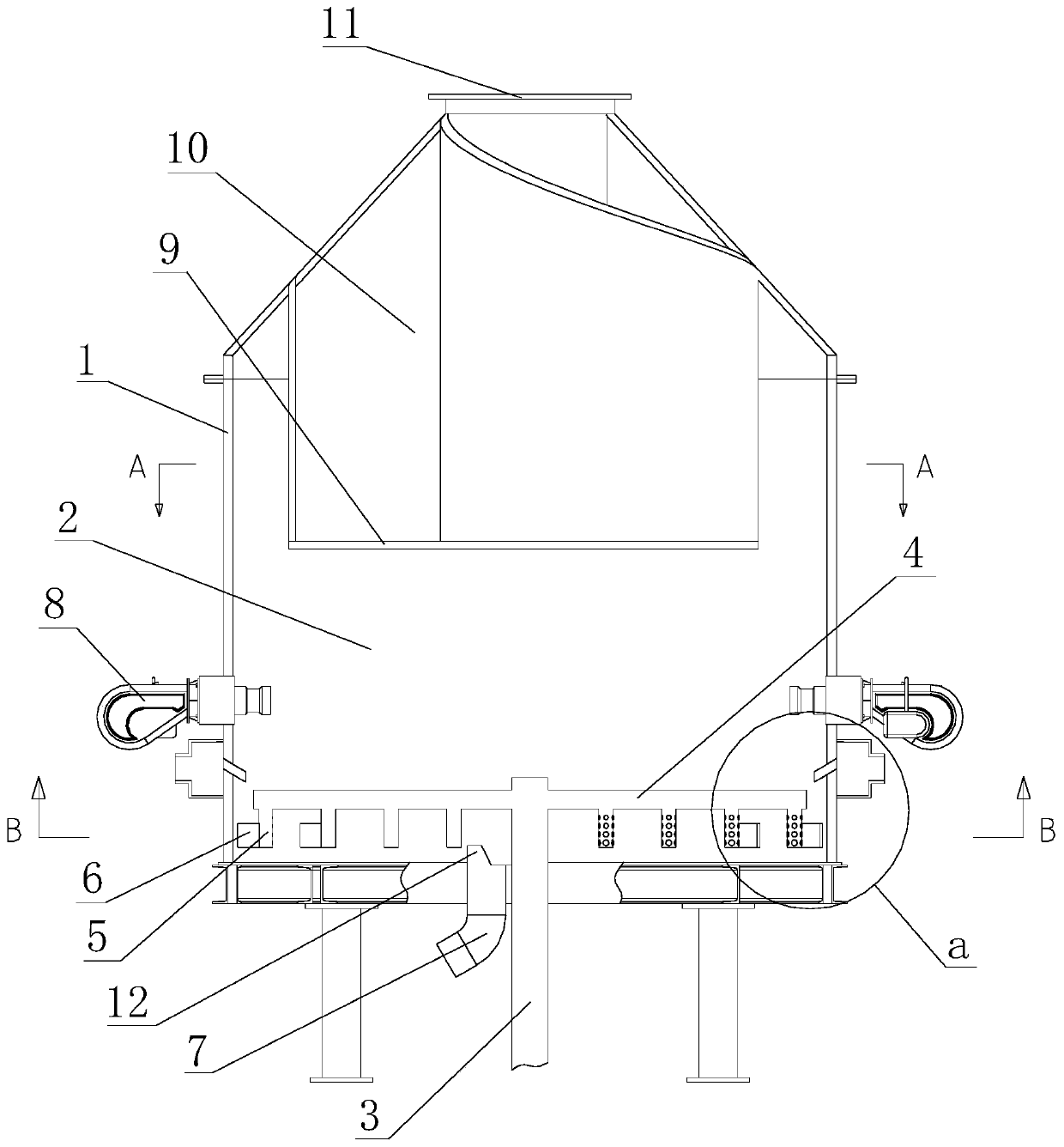
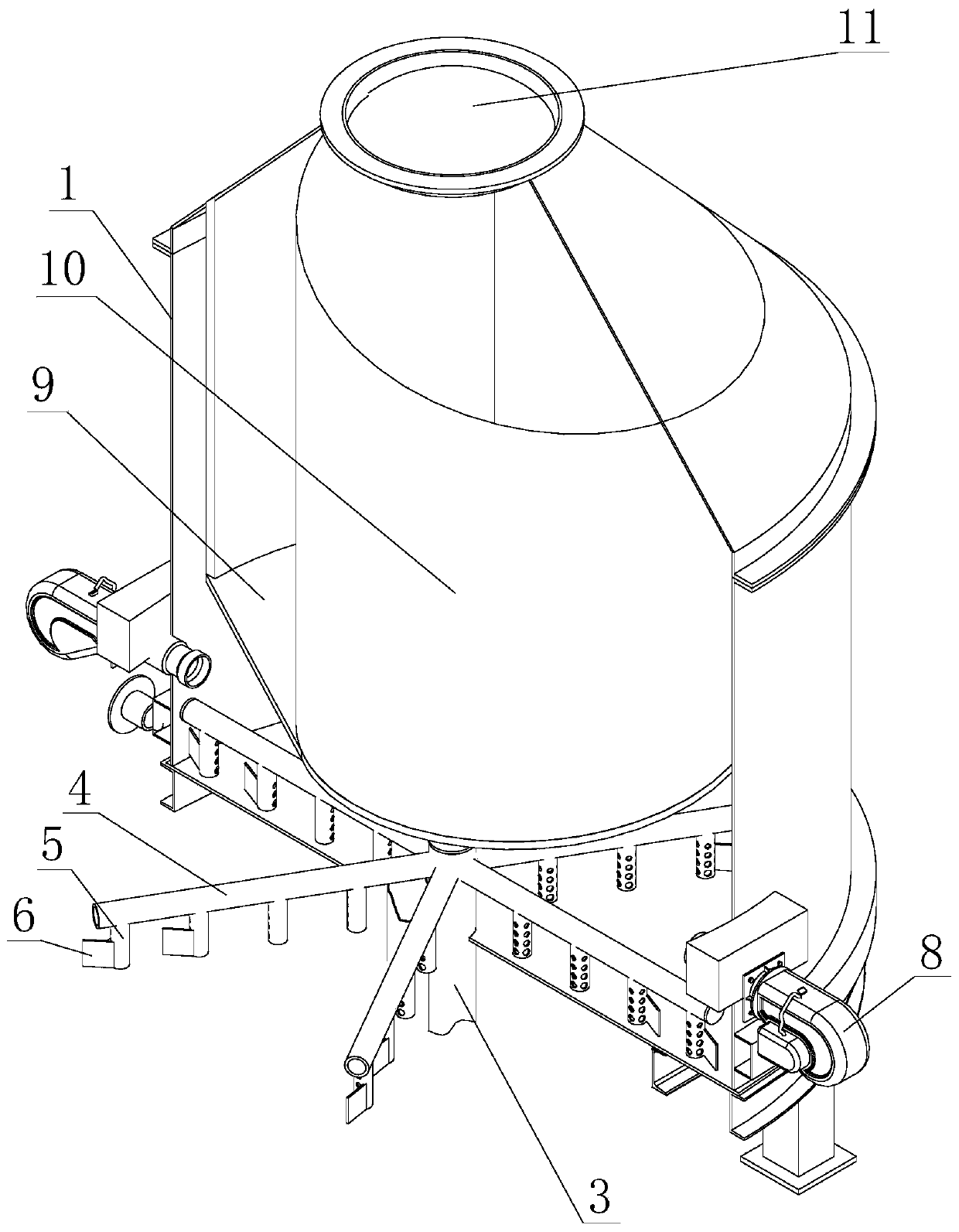
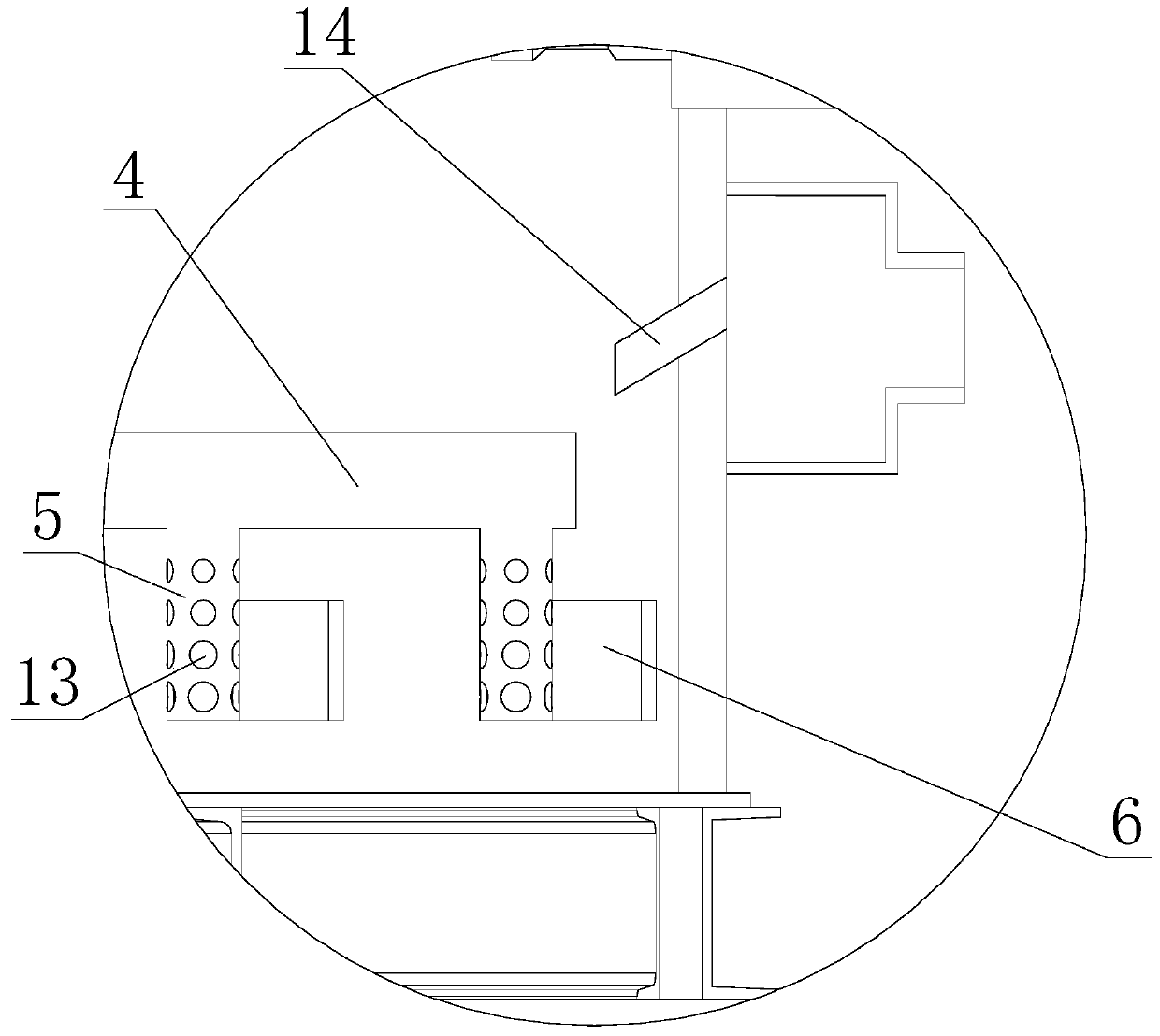
[0027] Such as Figure 1 to Figure 6 As shown, a clean incinerator includes a body of furnace 1. The body of furnace 1 is a double-layer structure. The outer layer of the furnace body 1 is an iron sheet, and the inner layer of the furnace body 1 is an insulating layer. The insulation layer is made of high alumina bricks, insulation bricks and insulation castables. A furnace 2 is arranged inside the furnace body 1 . A vertically arranged rotary shaft 3 is arranged at the center of the bottom of the furnace 2 . A slag discharge channel 7 is provided at the bottom of the furnace 2 . The slag discharge channel 7 is close to the rotary shaft 3 . The upper end of the slag discharge channel 7 is provided with a side baffle 12 . The side baffle is located on the upper side of the slag discharge channel, which can prevent the ash on one side from being discharged directly from the slag discharge channel, so that the ash at the bottom of the furnace can accumulate a certain thickn...

Embodiment 2

[0031] The difference between embodiment 2 and embodiment 1 is: in embodiment 2, the direction of the cyclone formed by the secondary oxygen supply port 14 when blowing air is opposite to the direction of rotation of the rotary shaft 3, and the rest of the structure is the same as that of embodiment 1.


PUM


Abstract

The invention discloses a clean incinerator. The clean incinerator comprises an incinerator body, wherein a hearth is arranged in the incinerator body, a rotation shaft which is vertically distributedis arranged in the center of the bottom of the hearth, a stirring arm is arranged on the rotation shaft, primary oxygen supply ports are formed in the stirring arm, a slag discharge channel is arranged at the portion, close to the rotation shaft, of the bottom of the hearth, a high-temperature combustion area is formed in the upper portion of the hearth, a vortex-shaped secondary combustion chamber is arranged in the high-temperature combustion area and is internally provided with a horizontal vortex combustion channel, and a smoke outlet is formed in the upper portion of the horizontal vortex combustion channel. According to the clean incinerator, the standing time of exhaust gas in a high-temperature area in the hearth can be prolonged, then harmful gas in the exhaust gas can be sufficiently combusted and decomposed, the content of harmful gas in the exhaust gas is lowered, and thus the pollution to the environment is lowered.

Description

technical field [0001] The invention relates to the technical field of sludge treatment, in particular to a clean incinerator. Background technique [0002] The treatment method with incineration as the core is the most thorough treatment method for solid waste. It can completely carbonize organic matter, kill pathogens, minimize the volume of sludge solid waste and realize energy recovery and utilization, and solve the problem of sludge solid waste. Finally deal with the problem. [0003] my country's sludge solid waste, such as municipal sludge, papermaking sludge, printing and dyeing sludge, etc., has low organic matter content, low calorific value, high moisture content, and is difficult to burn. In the actual treatment, the incinerator is used to incinerate the sludge solid waste. Sludge solid waste is incinerated in the incinerator, and the tail gas generated after incineration is directly discharged from the smoke outlet at the upper end of the incinerator. However...

Claims


Application Information

Patent Timeline
Patent Type & Authority Applications(China)
IPC IPC(8): F23G5/027F23G5/32F23G5/44
CPCF23G5/027F23G5/32F23G5/44F23G5/444
Inventor 项乐群李秀朝蓝丽梅吴天炳汪苏萍
Owner ZHEJIANG SANLIAN ENVIRONMENT MACHINERY EQUIP
Why Eureka
Try Eureka