
UUV path planning method based on particle swarm algorithm

A particle swarm algorithm and path planning technology, applied in navigation calculation tools, three-dimensional position/channel control, and independent decision-making process, can solve problems such as falling into traps, premature convergence, and affecting the efficiency and quality of UUV underwater operations

Active Publication Date: 2020-07-07
SHAANXI NORMAL UNIV
View PDF11 Cites 7 Cited by
  • Summary
  • Abstract
  • Description
  • Claims
  • Application Information

AI Technical Summary

Problems solved by technology

However, due to the existence of adjustable parameters such as population size, inertia weight, and acceleration coefficient, PSO has the problem of premature convergence and trapping in local optimal problems, and even lacks population diversity, resulting in non-optimal planning paths, which in turn affects Efficiency and quality of UUV underwater operations

Method used


Image

  • UUV path planning method based on particle swarm algorithm
  • UUV path planning method based on particle swarm algorithm
  • UUV path planning method based on particle swarm algorithm

Examples


Embodiment 1

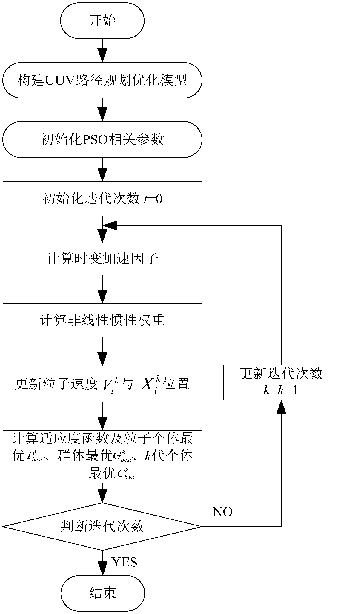
[0059] In order to solve the problem of premature convergence and trapping in PSO in the local optimal problem due to the existence of adjustable parameters such as population size, inertia weight and acceleration coefficient, and even lack of population diversity, resulting in non-optimal planning path, and then For issues that affect the efficiency and quality of UUV underwater operations, this embodiment provides a UUV path planning method based on particle swarm optimization, including the following steps:

[0060] Step 1: According to the path length f 1 , the repulsive potential field between the UUV and the obstacle and the attractive potential field f between the UUV and the target 3 Build UUV path planning optimization model f;

[0061] Step 2: Initialize PSO related parameters;

[0062] Step 3: Calculate the time-varying acceleration factor c through the relevant parameters 1 、c 2 and c 3 ;

[0063] Step 4: Calculate the nonlinear inertia weight w;

[0064] St...

Embodiment 2

[0112] In order to verify the feasibility and effectiveness of the UUV path planning method based on the particle swarm algorithm proposed in Embodiment 1, this embodiment uses a specific numerical simulation experiment to verify:

[0113] Specifically, it is assumed that the path planning model is established as follows: Suppose the UUV avoids 7 static obstacles (1#, 2#, 3#, 4#, 5#, 6#, 7#) and the UUV navigates from the starting point (0,0) Cross over to the target point (10000, 10000), represented by circles with different radii, the UUV’s motion speed is 5 knots (2.5 meters), and the initial heading angle is θ=45°; the static obstacle position information is shown in Table 1:

[0114] Table 1. Obstacle position information and radius

[0115] obstacle Location radius obstacle Location radius 1# (3265,3509) 900 5# (6508,2030) 900 2# (2600,917) 600 6# (5250,6500) 1300 3# (1783,7450) 1200 7# (8502,5000) 800 4# (8034,7560) 6...


PUM


Abstract

The invention relates to a UUV path planning method based on a particle swarm algorithm. The UUV path planning method comprises the following steps: S1, constructing a UUV path planning optimization model f according to a path length f1, a repulsion potential field between a UUV and an obstacle and an attraction potential field f3 between the UUV and a target; S2, initializing PSO related parameters; S3, calculating time-varying acceleration factors c1, c2 and c3 through the related parameters; S4, calculating a nonlinear inertia weight w; S5, calculating a particle speed Vik and a particle position Xik through the time-varying acceleration factors c1, c2 and c3 and the nonlinear inertia weight w; S6, updating the optimal population of the particle individuals and the optimal population ofthe kth generation of particle individuals by evaluating the fitness function f; S7, judging the number of iterations, if the number of iterations k reaches the maximum number T, outputting an optimal result, and stopping operation; otherwise, k = k + 1, and returning to S4; according to the invention, the balance between the global search capability and the local search capability can be realized, and the UUV path planning solution can be efficiently and flexibly realized.

Description

technical field [0001] The invention belongs to the field of underwater unmanned systems, and in particular relates to a UUV path planning method based on a particle swarm algorithm. Background technique [0002] With the popularization and wide application of Unmanned Underwater Vehicle (UUV) in the fields of marine engineering and military operations, UUV, as a necessary intelligent unmanned underwater vehicle, has attracted widespread attention at home and abroad. Path planning research is one of the most challenging problems in the field of UUV applications, because it is the basis for ensuring UUVs to complete complex underwater tasks safely and efficiently. The main goal of UUV path planning is; to calculate the optimal collision-free shortest path from the start point to the end point in the underwater environment. [0003] UUV path planning problems can be divided into two categories: local path planning (local path planning, LPP) and global path planning (global pa...

Claims


Application Information

Patent Timeline
IPC IPC(8): G05D1/10G01C21/20
CPCG05D1/10G05D1/0088G01C21/20Y02T10/40
Inventor 梁洪涛朱鑫徐建华
Owner SHAANXI NORMAL UNIV
Learn More