Polymer coating mixing equipment

A polymer and coating technology, used in mixers, shaker/oscillation/vibration mixers, mixers with rotary stirring devices, etc., which can solve the damage of transmission parts, the small amount of single mixing, and affect the coating effect, etc. problem, to achieve the effect of increasing the storage capacity

Inactive Publication Date: 2020-07-10
宋红龙
View PDF0 Cites 0 Cited by
  • Summary
  • Abstract
  • Description
  • Claims
  • Application Information

AI Technical Summary

Problems solved by technology

[0004] The main purpose of the present invention is to overcome the deficiencies of the prior art and provide a kind of polymer paint mixing equipment to solve the problem that the existing mixers generally use solvent-based and water-based paints together, and only use vibration or rotary mixers. The same mixing

Method used


Image

  • Polymer coating mixing equipment
  • Polymer coating mixing equipment
  • Polymer coating mixing equipment

Examples


Embodiment 1

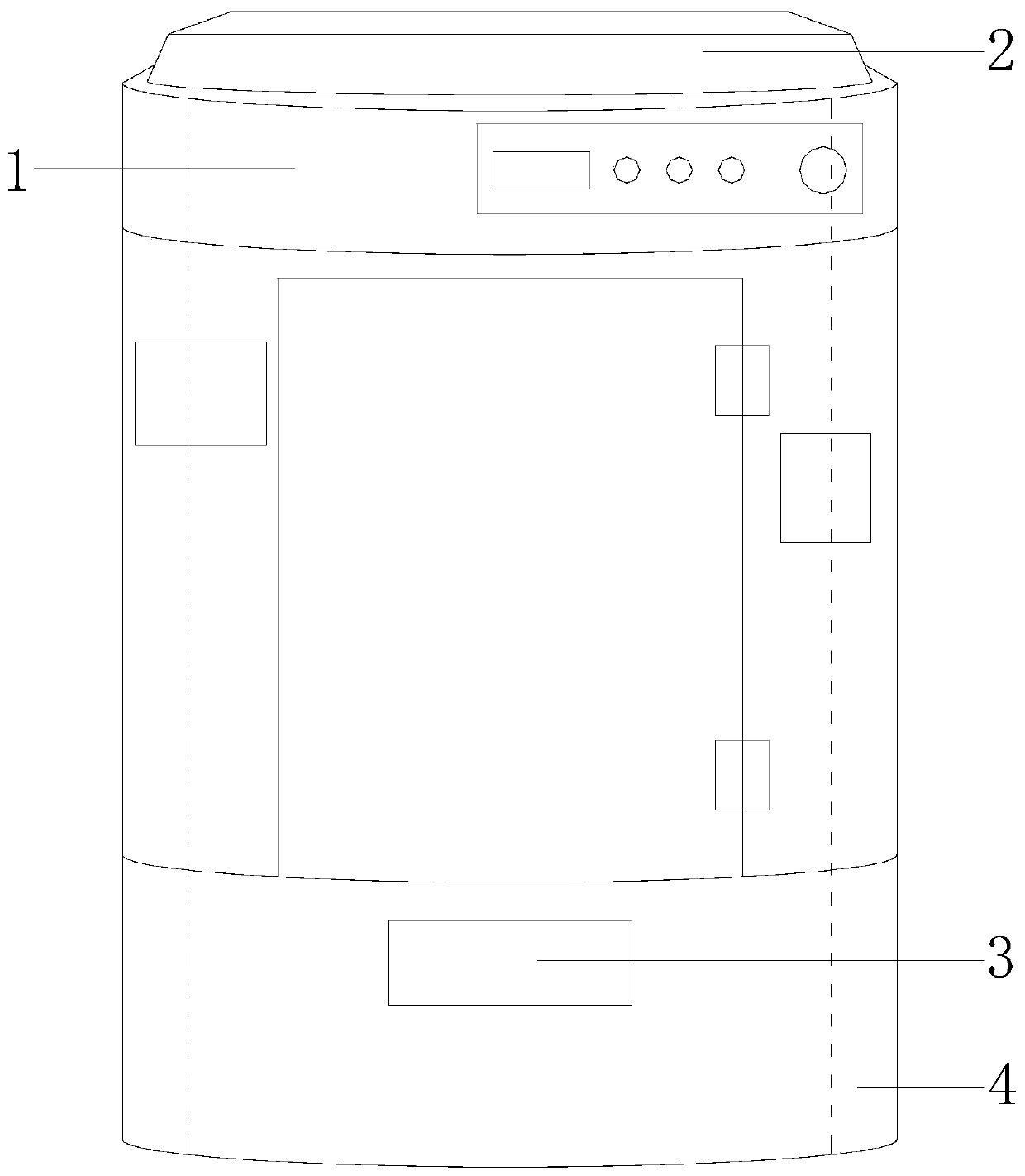
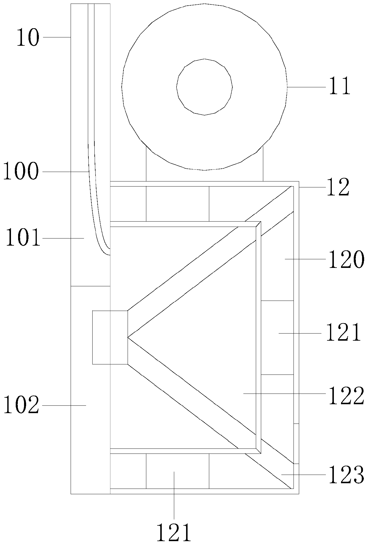
[0027] Example 1 please refer to Figure 1-2 , The present invention provides a technical solution for polymer coating mixing equipment: its structure includes a mixing device 1, a feeding top frame 2, a material outlet 3, and a machine frame 4, and the mixing device 1 is installed inside the machine frame 4. , the feeding top frame 2 is locked with the upper end of the machine frame 4, the discharge port 3 is installed at the front end of the machine frame 4, and the mixing device 1 is composed of a feeding structure 10, a motor 11, and a mixing cylinder 12. The feeding structure 10 is installed and connected to the left end of the mixing cylinder 12, the bottom of the motor 11 is locked on the mixing cylinder 12, and the feeding structure 10 includes an arc hopper 100, a feeding upper frame 101, and a feeding bottom frame 102 , the arc bucket 100 is mounted on the feeding upper frame 101 and the two form an integrated structure, the bottom of the feeding upper frame 101 is a...

Embodiment 2

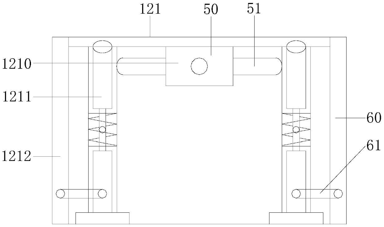
[0029] Example 2 please refer to Figure 3-7, the present invention provides a technical solution for a polymer coating mixing equipment: the vibrator 121 includes a vibration motor 1210, a vibration rod 1211, and a vibration frame 1212. The vibration motor 1210 is locked inside the vibration frame 1212, so The left and right sides of the vibration motor 1210 are attached to the vibration rod 1211. The vibration rod 1211 is composed of three parts, and the middle part plays a main swing role. The upper and lower ends of the vibration rod 1211 are installed and connected to the vibration machine frame 1212. The vibration motor 1210 includes a motor body 50 and a push rod 51 . The ring side of the motor body 50 is installed and connected to the push rod 51 . The vibration frame 1212 includes a frame body 60 and a limit bar 61 . The frame body 60 It is connected with the right end shaft of the limiting rod 61. The limiting rod 61 acts as a limit to the swing of the vibration rod ...


PUM


Abstract

The invention discloses polymer coating mixing equipment. The equipment structurally comprises a mixing device, a feeding top frame, a discharge port and a machine frame. The mixing device is mountedon the machine frame; the feeding top frame is locked with the machine frame, the discharge port is formed in the machine frame, the mixing device is composed of a feeding structure, a motor and a mixing barrel, the feeding structure is connected to the mixing barrel, the motor is locked on the mixing barrel, the feeding structure comprises an arc hopper, a feeding upper frame and a feeding bottomframe. The arc hopper is embedded in the feeding upper frame, and the feeding upper frame and the feeding bottom frame are connected in an assembled mode. The mixing barrel comprises an outer barrel,a vibrator, an inner mixing barrel and a stirrer, the vibrator is locked with the outer barrel and the inner mixing barrel, and the inner mixing barrel is in mounting connection with the stirrer. According to the polymer coating mixing equipment, vibration type transmission of the vibrator and rotary type transmission of the stirrer are achieved, different coatings are mixed in different mixing modes, damage cannot be caused due to separate transmission, the length of a stirring rod can be changed according to the mixing amount, and the storage amount of the inner mixing barrel is increased.

Description

technical field [0001] The invention relates to the field of paint mixing equipment, in particular to a polymer paint mixing equipment. Background technique [0002] Organic polymer coatings are divided into two categories: solvent-based and water-based coatings. The mixers are generally divided into two types: vibrating and rotary. The vibrating type vibrates up and down, back and forth, left and right, and the rotary type rotates 360 degrees to mix the coatings completely. [0003] Prior art The existing mixers generally use solvent-based and water-based paints together, and use a single vibrating or rotary mixing. The ingredients of the raw materials are different, and the same mixing method will affect the smearing effect of the paint. Changing the mixing method will cause damage to the transmission components, and due to the transmission requirements, the volume of the mixing tank will be limited to a certain extent, and the amount of single mixing is small. SUMMARY O...

Claims


Application Information

Patent Timeline
IPC IPC(8): B01F11/00B01F7/04B01F7/02
CPCB01F27/0541B01F27/192B01F27/60B01F27/70B01F31/56B01F31/70B01F2101/30
Inventor 宋红龙
Owner 宋红龙
Why Eureka
Try Eureka