Optical alignment debugging process and optical tool setting device of clamping diamond micro milling cutter

An optical alignment and diamond technology, applied in workpiece clamping devices, manufacturing tools, hand-held tools, etc., can solve problems that restrict the development of ultra-precision micro-milling technology, assembly accuracy errors, etc., to improve the quality of the processed surface and achieve precise Assembly, reduce overcut effect

Active Publication Date: 2021-11-09
江苏普锐斯钻石工具有限公司
View PDF5 Cites 0 Cited by
  • Summary
  • Abstract
  • Description
  • Claims
  • Application Information

AI Technical Summary

Problems solved by technology

At present, the assembly accuracy error of clamp-type diamond micro-milling cutters available on the market is more than tens of microns, which has a serious impact on diamond micro-milling cutters with a radius of gyration of only a few hundred microns, further restricting ultra-precision The Development of Micro Milling Technology

Method used


Image

  • Optical alignment debugging process and optical tool setting device of clamping diamond micro milling cutter
  • Optical alignment debugging process and optical tool setting device of clamping diamond micro milling cutter
  • Optical alignment debugging process and optical tool setting device of clamping diamond micro milling cutter

Examples


Embodiment 1

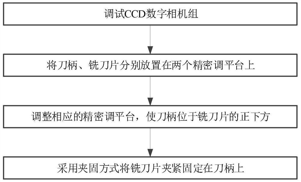
[0018] For diamond micromilling cutters assembled with high precision, see figure 1 , present embodiment 1 provides a kind of optical alignment debugging process of clamping type diamond micro-milling cutter, comprises the following steps: step S1, debugging CCD digital camera group; on a precision adjustment platform; step S3, within the imaging field of view of the CCD digital camera group, adjust the corresponding precision adjustment platform so that the handle is positioned directly below the milling blade; and step S4, clamp the milling blade in a clamping manner Tightly fastened to the handle.

[0019] Optionally, the tool holder is a carbide tool holder, and the milling blade is a diamond milling blade.

[0020] Optionally, the clamping method is, for example but not limited to, a combination of a pressing plate and a screw.

[0021] Optionally, the debugging CCD digital camera group includes: step S11, setting corresponding CCD digital cameras in the horizontal dire...

Embodiment 2

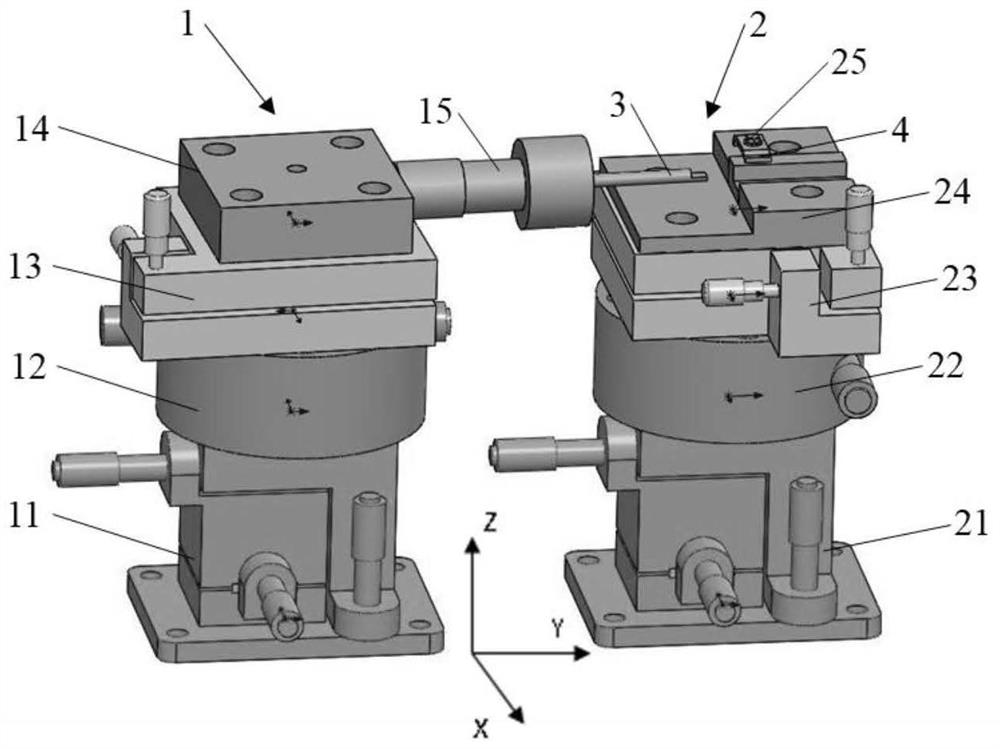
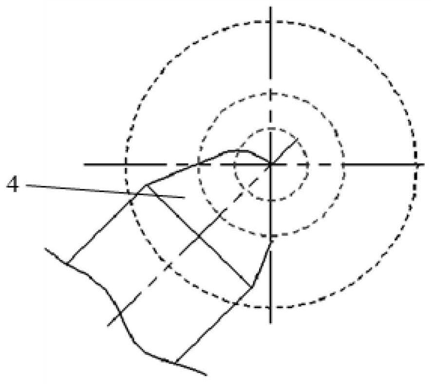
[0029] On the basis of embodiment 1, see figure 2 , the present embodiment 2 provides a clamping type diamond micro-milling cutter optical tool setting device, including: CCD digital camera group (as long as the tool handle debugging assembly 1, milling blade debugging assembly 2, tool handle 3, milling blade 4 Just within the imaging field of view of the CCD digital camera group, not shown in the figure), tool handle debugging component 1, milling blade debugging component 2; within the imaging field of view of the CCD digital camera group, adjust the tool handle debugging component 1, The milling blade debugging assembly 2 makes the tool handle 3 directly below the milling blade 4, so that the milling blade 4 is clamped and fixed on the tool handle 3 by clamping.

[0030] Optionally, the CCD digital camera group includes CCD digital cameras respectively arranged in the horizontal direction and the vertical direction, that is, a horizontal CCD digital camera and a vertical C...


PUM


Abstract

The invention belongs to the technical field of tool manufacturing, and in particular relates to an optical alignment debugging process and an optical tool setting device of a clamping type diamond micro milling cutter. The optical alignment debugging process of the clamping type diamond micro milling cutter includes: step S1, debugging the CCD digital camera group; step S2, placing the handle and the milling blade on two precision adjustment platforms; step S3, Within the imaging field of view of the CCD digital camera group, adjust the corresponding precision adjustment platform so that the tool handle is located directly below the milling blade; and step S4, clamping and fixing the milling blade on the tool handle by clamping. The precise coincidence of the rotation axis of the cutter head of the milling insert and the rotation axis of the tool holder is realized, and it is used to complete the high-precision assembly of the milling insert and the tool holder.

Description

technical field [0001] The invention belongs to the technical field of tool manufacturing, and in particular relates to an optical alignment debugging process and an optical tool setting device of a clamping type diamond micro milling cutter. Background technique [0002] The radius of gyration of the arc edge diamond micro milling cutter head is very small, generally within 500μm, and the smallest even reaches 20-30μm. The number of teeth of traditional metal milling cutters is generally greater than two. The more teeth of the milling cutter, the smoother the milling process, the higher the efficiency, and the guaranteed processing quality. However, due to the high hardness and high brittleness of diamond crystal materials, it is difficult to use traditional mechanical sharpening technology to sharpen multi-tooth complex cutter heads, so it is difficult to make multi-edged diamond milling cutter heads. Even though special processing technologies such as ultra-short pulse l...

Claims


Application Information

Patent Timeline
Patent Type & Authority Patents(China)
IPC IPC(8): B25B27/14B25B11/02
CPCB25B11/02B25B27/14
Inventor 宗文俊程晓
Owner 江苏普锐斯钻石工具有限公司
Why Eureka
Try Eureka