Drying, smell removal and cooling device for plastic

A cooling device and drying technology, applied in the separation of dispersed particles, chemical instruments and methods, separation methods, etc., can solve the problems of long cooling time of cooling liquid, long drying time, restricting the development of enterprises, etc., so as to reduce the drying time. , the effect of speeding up drying and cooling, and speeding up the drying process

Active Publication Date: 2020-07-10
内江金方格工业有限公司
View PDF6 Cites 0 Cited by
  • Summary
  • Abstract
  • Description
  • Claims
  • Application Information

AI Technical Summary

Problems solved by technology

However, drying plastic pellets only through heated airflow not only requires high energy consumption, but also takes a long time to dry, resulting in a large proportion of drying in plastic production costs.
Especially in recent years, the increase in the requirements for the removal of plastic odors has led to the need for multiple dryings of plastics, which has greatly increased the production costs of plastic manufacturers and severely restricted the development of related companies.
[0004] Moreover, after the plastic pellets are dried at high temperature, the pellets need to be cooled again, and the cooling method is mostly cooling liquid cooling, and the cooling liquid takes away the heat emitted by the plastic pellets to achieve the cooling effect, but the plastic pellets have It may be that during the cooling process, due to the high temperature generated by the accumulation, it will stick together, which will affect the use of plastic pellets, and the time to cool down with cooling liquid is relatively long

Method used


Image

  • Drying, smell removal and cooling device for plastic
  • Drying, smell removal and cooling device for plastic
  • Drying, smell removal and cooling device for plastic

Examples


Embodiment

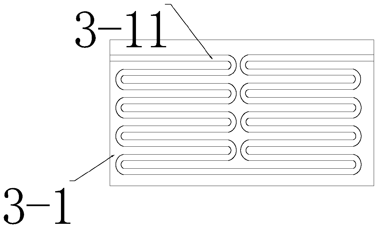
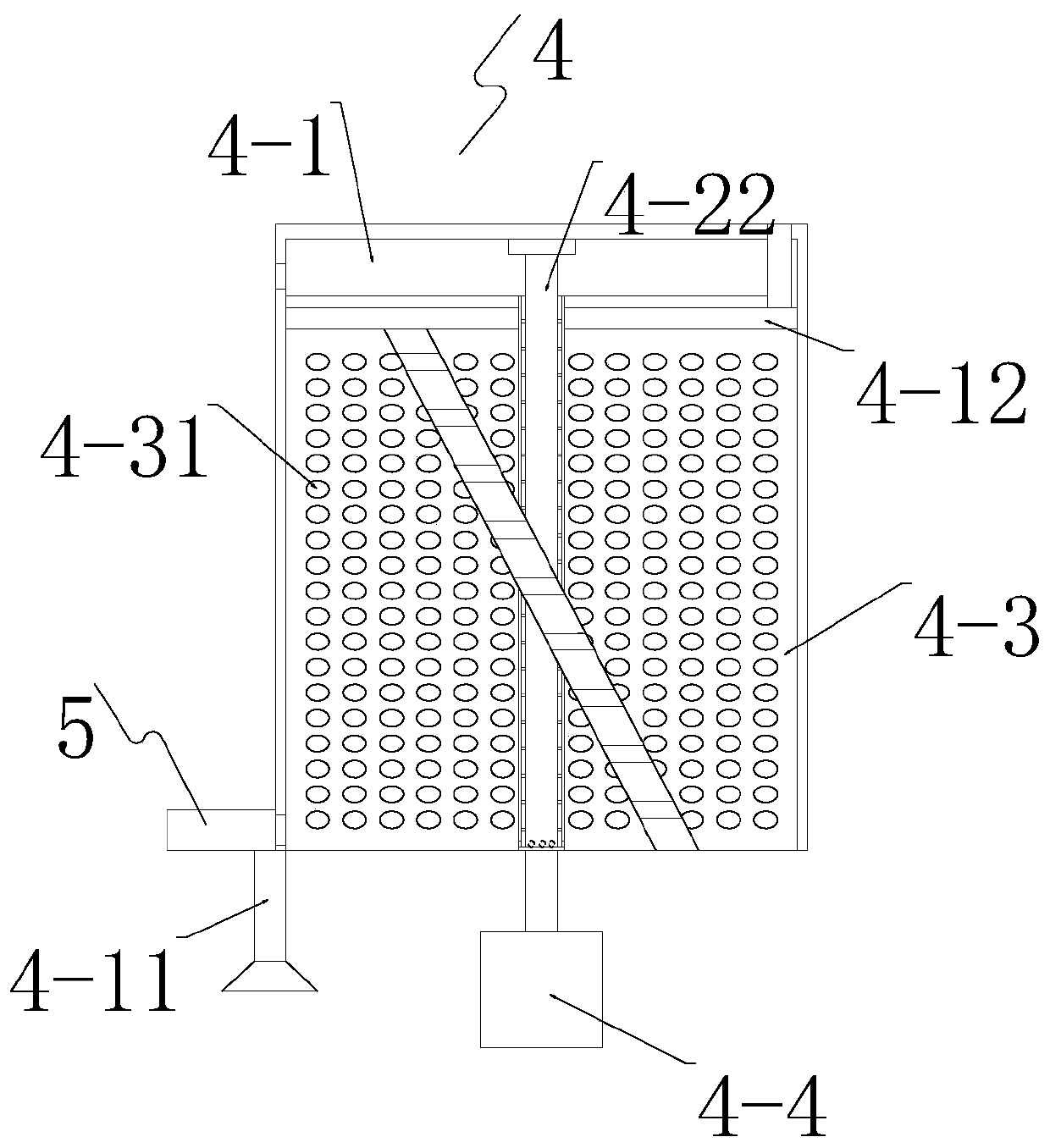
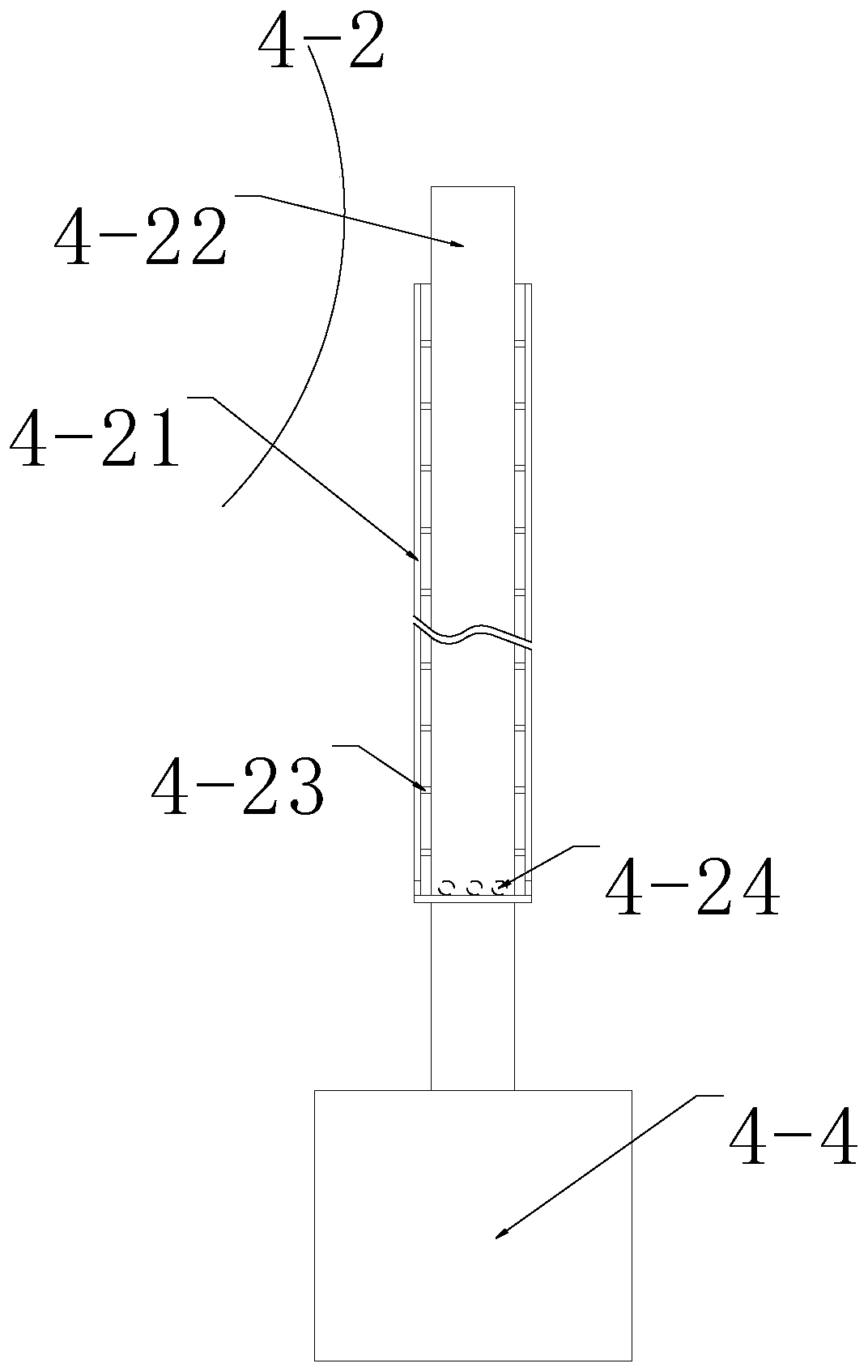
[0027] Example: such as Figure 1-9 As shown, a drying and deodorizing cooling device for plastics includes a bracket 1, a drying mechanism 2, a deodorizing heat dissipation mechanism 3, and a cooling mechanism 4. The drying mechanism 2 is sequentially installed on the bracket 1 from top to bottom. , Cooling mechanism 4. Deodorizing and heat dissipation mechanism 3 and drying mechanism 2 are sequentially installed on the bracket 1 from left to right. The drying mechanism 2 makes the plastic pellets fall from a high place and performs high temperature drying of the plastic pellets, deodorizing and heat dissipation mechanism 3 The high-temperature water vapor generated by the drying mechanism 2 is deodorized and dissipated, and the cooling mechanism 4 is provided with air required for cooling. The cooling mechanism 4 causes the plastic pellets to fall from a height and cools and air-dry the plastic pellets.

[0028] The models of all motors involved in this device are JSF 42-3-30-A...


PUM


Abstract

The invention discloses a drying, smell removal and cooling device for plastic. The drying, smell removal and cooling device for plastic comprises a support, a drying mechanism, a smell removal and heat dissipation mechanism and a cooling mechanism. The support is provided with the drying mechanism and the cooling mechanism in sequence from top to bottom. The support is provided with the smell removal and heat dissipation mechanism and the drying mechanism in sequence from left to right. The drying mechanism enables plastic particles to fall off from a high place and carries out high-temperature drying on the plastic particles. The smell removal and heat dissipation mechanism carries out smell removal and heat dissipation treatment on high-temperature water vapor generated by the drying mechanism and provides the cooling mechanism with the air needed for cooling. The cooling mechanism enables the plastic particles to fall off from a high place and carries out cooling air-drying on theplastic particles. The drying, smell removal and cooling device for plastic is scientific, reasonable, and safe and convenient to use; and because the drying mechanism enables the plastic particles tofall off from the high place to carry out free-fall motion, and the drying mechanism carries out drying treatment on the plastic particles falling off from the high place by utilizing spiral high-temperature air flow, the plastic particles make full contact with the high-temperature air flow to be dried in the falling process.

Description

Technical field [0001] The invention relates to the technical field of plastic drying and deodorizing cooling, in particular to a drying and deodorizing cooling device for plastics. Background technique [0002] In the plastic manufacturing industry, due to the degree of drying of plastic pellets and the transparency of the final product, the purity of the color, including mechanical properties such as bending, torsion, elasticity, tensile index, yield, and electrical properties including insulation, conductivity, etc. Relevant, therefore, the plastic pellets must be dried before they are sent to injection molding machines, extruders, blister machines or other plastic processing machinery. [0003] So far, many drying methods for plastic material pellets have been proposed, but the most widely used method is the dry air method, that is, the heated air flows through the plastic pellets to remove the corresponding moisture therefrom. However, only the heated airflow is used to dry t...

Claims


Application Information

Patent Timeline
Patent Type & Authority Applications(China)
IPC IPC(8): B29B13/06B29B13/04B29B13/00
CPCB29B13/065B29B13/045B01D53/04B01D53/261B01D2253/102
Inventor 陶怡君
Owner 内江金方格工业有限公司
Why Eureka
Try Eureka