
Material sending module and screen printing machine

A technology of feeding and feeding hoppers, which is applied in the field of feeding modules and screen printing machines, which can solve the problems of manufacturing costs, high maintenance costs in later use, and the inability of fully automatic screen printing machines to be popularized in a large area, reducing manual participation in screen printing To achieve the effect of simple structure, strong competitiveness, and reduced manufacturing and post-maintenance costs

Inactive Publication Date: 2020-07-10
CHONGQING BOYAN IND DESIGN CO LTD
View PDF0 Cites 12 Cited by
  • Summary
  • Abstract
  • Description
  • Claims
  • Application Information

AI Technical Summary

Problems solved by technology

[0003] Screen printing machines are already a very mature technology, but the current screen printing machines are mostly semi-automatic, which is specifically manifested in the need for manual loading and unloading. With the increasing development of unmanned factory technology, manual labor is obviously an important part of manufacturing. The most expensive link, so reducing the manual participation in screen printing is an urgent problem to be solved at present
[0004] Of course, there are also fully automatic screen printing machines at present, but their structures are relatively complicated and require a large number of motors, cylinders, and oil cylinders. Therefore, their manufacturing costs, later use costs, and maintenance costs are relatively high, and sometimes even exceed labor costs. This is the pain point that the current automatic screen printing machine has not been widely popularized

Method used


Image

  • Material sending module and screen printing machine
  • Material sending module and screen printing machine
  • Material sending module and screen printing machine

Examples


Embodiment Construction

[0023] The technical solutions in the embodiments of the present invention will be clearly and completely described below with reference to the accompanying drawings in the embodiments of the present invention.

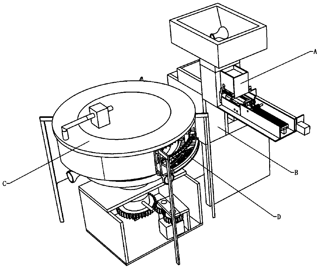
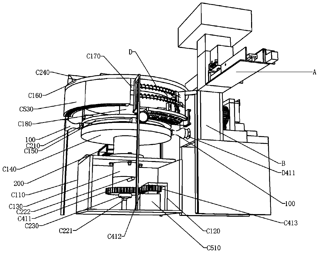
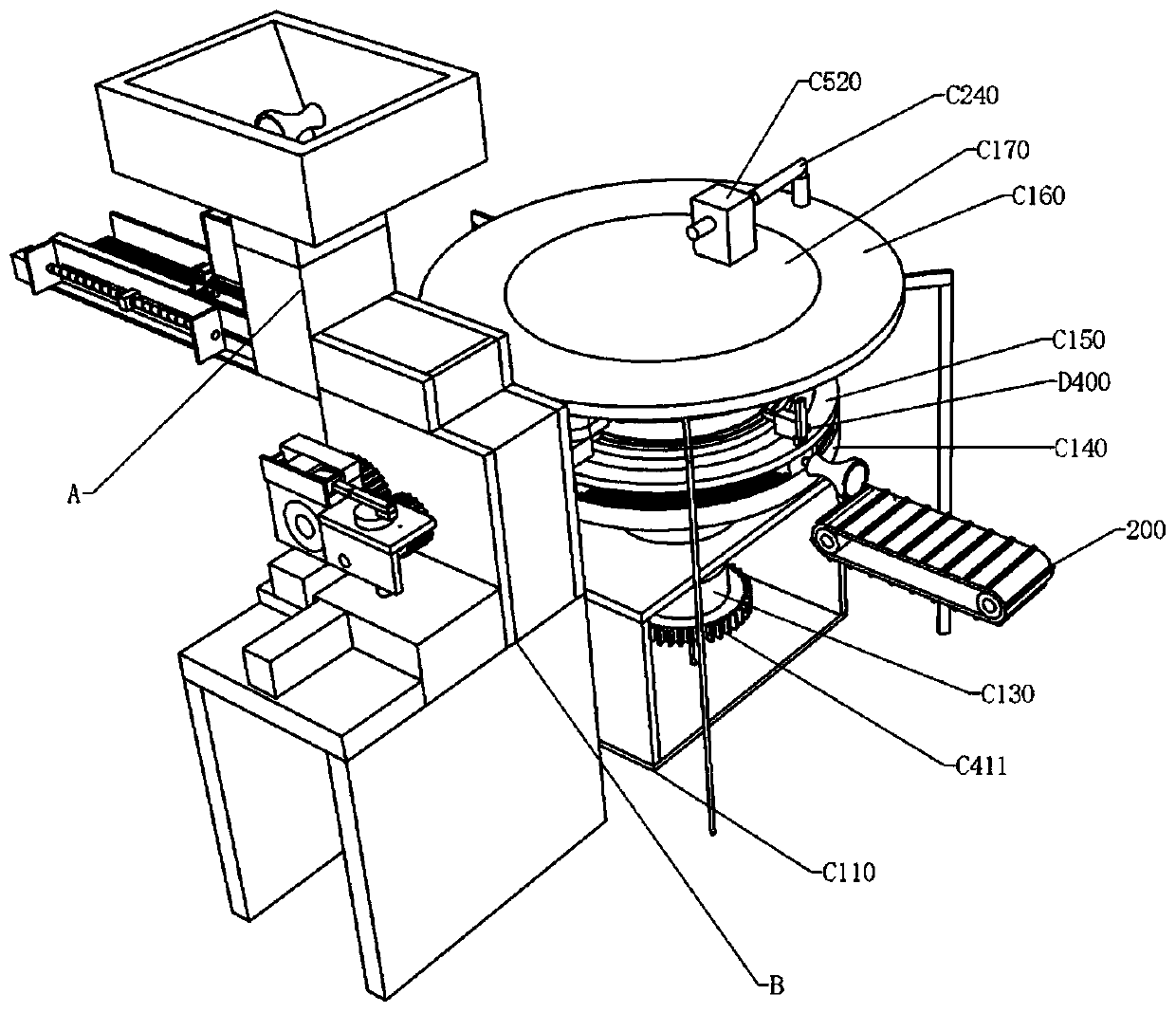
[0024] see Figure 1-Figure 3 , the screen printing machine of this embodiment includes:

[0025] The feeding module A is used to transport the substrates 100 to the feeding module B one by one;

[0026] The feeding module B is used to set the substrates 100 on the conveying shaft of the host one by one to complete the feeding of the substrates one by one;

[0027] The host C is used to drive the substrate to move to different stations, and connect different power according to the station design to complete the loading, printing, drying and unloading of the substrate;

[0028] The printing module D prints the substrate through the first squeegee, the second squeegee and the silk screen;

[0029] The discharge conveyor belt 200 is used to output the printed substrate...


PUM


Abstract

The invention discloses a material sending module and a screen printing machine. The screen printing machine includes the material sending module, a feeding module, a main machine, a printing module and a discharging conveyor belt; the material sending module is used for conveying printing stock to the feeding module one by one; the feeding module is used for enabling the printing stock to sleevea conveying shaft of the main machine one by one to complete the feeding of the printing stock one by one; the main machine is used to drive the printing stock to move to different stations; the printing module is used to print the printing stock through a first squeegee, a second squeegee and a screen; and the discharging conveyor belt is used to conveying the printed printing stock out of the main machine to complete discharging. The screen printing machine is simple in structure, few in the usage amount of power equipment and very convenient to maintain. In addition, materials can be sent to the material sending module through an existing manipulator, a vibrating plate and the like so as to realize the full-automatic feeding, printing and discharging, manual participation are not neededin the whole process, the labor cost is greatly reduced, 24-hour uninterrupted production is realized, high competitiveness is provided for enterprises, and the market space is wide and the economicvalue is high.

Description

technical field [0001] The invention relates to printing technology, in particular to a feeding module and a screen printing machine thereof. Background technique [0002] Screen printing machine, also known as screen printing machine, mainly sets through holes on the screen, and forms a certain pattern through the through holes and non-through holes, and then presses the screen on the substrate through a scraper, and then moves the screen. A screen or a squeegee makes the substrate move along the screen to squeeze the ink on the side of the screen away from the substrate, pass through the screen and print on the substrate to complete the printing of the substrate. Screen printing machines are widely used in packaging technology, advertising printing technology, textile printing technology, bottle (tubular) printing technology, etc. [0003] Screen printing machines are already a very mature technology, but most of the current screen printing machines are in semi-automatic ...

Claims


Application Information

Patent Timeline
Patent Type & Authority Applications(China)
IPC IPC(8): B41F15/44B41F15/18B41F15/12B41F15/14B41F15/08B65G37/00B65G47/82
CPCB41F15/08B41F15/12B41F15/14B41F15/18B41F15/44B65G37/00B65G47/82
Inventor 刘钟元
Owner CHONGQING BOYAN IND DESIGN CO LTD
Learn More