Gear transmission type mechanical anti-theft lock

A mechanical anti-theft lock and gear transmission technology, applied in building locks, keys, buildings, etc., can solve the problems of high processing precision and high manufacturing cost

Active Publication Date: 2020-07-10
BEIHUA UNIV
View PDF21 Cites 3 Cited by
  • Summary
  • Abstract
  • Description
  • Claims
  • Application Information

AI Technical Summary

Problems solved by technology

[0006] Along with technology development, a number of patented products with "lock cylinder fixed cross mechanical anti-theft lock" as the core technology in the later period, including "lock cylinder fixed cross mechanical anti-theft lock matching fingerprint lock" (ZL201610990489.0), "a Cam Mechanism for Fingerprint Lock" (ZL201611045195.7), "Double Plug-in Anti-theft Door and External Locking Device" (ZL201610129609.8), "A Forced Reset Device for Rotating Ring of Anti-theft Lock" (ZL201710390280.5), " Cam Mechanism of Fingerprint Lock and Forced Reset Device of Rotating Ring" (ZL201710435512.4), "Automatic Reset and Idling Device of Stop Handle" (ZL201710393215.8), "Single Clutch Cam Mechanism of Fingerprint Lock" (ZL201810363492.9) , "Press-down assembly tool for anti-theft lock cam me

Method used


Image

  • Gear transmission type mechanical anti-theft lock
  • Gear transmission type mechanical anti-theft lock
  • Gear transmission type mechanical anti-theft lock

Examples


Embodiment approach 1

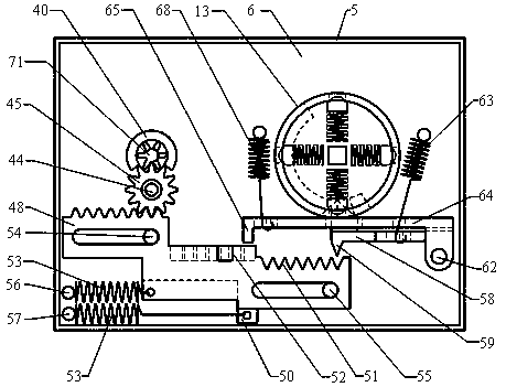
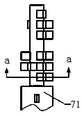
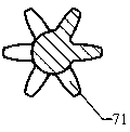
[0071] Such as figure 1 , 29 , 37, a lock body 1 of a gear transmission type mechanical anti-theft lock includes an outer plate 2, a partition plate 3, an inner plate 4 and a coaming plate 5, and the rectangular cavity between the outer plate 2 and the partition plate 3 is the outer cavity Body 6, the rectangular cavity between the partition plate 3 and the inner side plate 4 is the inner cavity body 7, the side of the outer side plate 2 that is located outside the lock body 1 is the outer side 8 of the lock body, and the side of the inner side plate 4 that is located outside the lock body 1 The side is the inner side 9 of the lock, and the inner side of the door outer panel 11 is provided with a reinforcing plate 12, the lock body 1 is fixedly mounted on the reinforcing plate 12, and the outer side 8 of the lock is in contact with the reinforcing plate 12. The outer side of the door leaf outer panel 11 is provided with a lock outer panel 69, and is assembled with a handle r...

Embodiment approach 2

[0105] Such as Figure 38 , 39As shown, the position of the parts of the unlocking control mechanism in Embodiment 1 is rearranged, the principle remains the same, and the performance of the lock remains unchanged: that is, the position of the center of the key hole remains unchanged, and it is still on the same horizontal line as the center of the cam mechanism, and is located on the cam On the left side of the mechanism, the rectangular long hole 43 is located on the top of the circular tube 40, the gear shaft 44 and the intermediate gear 45 are located directly above the circular tube 40, the left end of the rack is located above the intermediate gear 45, and the middle and right ends of the rack are located at the top of the circular tube 40. Above the cam 13, the locking plate 58 and the unlocking plate 64 are located between the right end of the rack and the cam 13, wherein the unlocking plate 64 is located under the locking plate 58 and above the cam 13, and the spring ...

Embodiment approach 3

[0108] Such as Figure 40 As shown, the following alternatives can also be adopted, the principle remains the same, and the original performance of the lock remains unchanged: the centers of the circular tube 40, the gear shaft 44, the intermediate gear 45 and the center of the cam mechanism are all placed on the same horizontal line, and each The rack runs reciprocatingly in the vertical direction, that is, the parts positions of the unlocking control mechanism are from left to right: the round tube 40 where the keyhole 41 is located, the intermediate gear 45, the vertical rack, the locking plate 58, the unlocking plate 64, The cam 13, the corresponding sliding shaft A54 and the sliding shaft B55 are respectively placed on the upper and lower parts of the outer cavity body 6, and the corresponding spring connecting posts A56 and spring connecting posts B57 are also placed on the upper and lower parts of the outer cavity body 6 respectively. The straight rack parts of A48 and ...


PUM


Abstract

The invention discloses a gear transmission type mechanical anti-theft lock, and relates to the field of mechanical anti-theft locks. The gear transmission type mechanical anti-theft lock is characterized in that a key hole and a handle rotating shaft are horizontally arranged, a key is formed by connecting a plurality of pinions in series, each pinion is a complete gear or an incomplete gear or has zero teeth, and the key drives each rack to run for different distances through an intermediate gear. After the key is rotated by a circle, a handle drives a cam to push a locking plate to be inserted into sawteeth of the racks firstly, the racks cannot move any more, the cam pushes an unlocking inserting plate to be inserted into rectangular openings of the racks, and the cam continues to rotate to achieve unlocking. If the key is incorrect, the locking plate still clamps all the racks and cannot move, but the unlocking inserting plate cannot be inserted into the rectangular openings, so that the cam is prevented from continuously rotating, and the lock cannot be unlocked; if the handle is strongly twisted, the handle idles; and the lock is locked only needing to reversely lift the handle without the key. The mechanism is simple in structure, low in manufacturing cost and easy to install, and the lock has the characteristics of technical unlocking prevention, damage unlocking prevention, large secret key amount, stability, durability and the like.

Description

technical field [0001] The invention relates to the field of mechanical anti-theft locks, in particular to a gear transmission type mechanical anti-theft lock. Background technique [0002] At present, common mechanical anti-theft locks in the prior art mainly include tumbler locks, blade locks and hybrid anti-theft locks of the two. Among them, according to the structure of the tumbler lock, the shape of the key can be divided into ordinary single-sided tooth pattern (commonly known as a word lock), double-sided tooth pattern, cross-shaped tooth pattern, single-row or double-row round pits, etc.; the key corresponding to the leaf lock There are one or two serpentine curved grooves on the top; the key of the hybrid anti-theft lock has both serpentine curved grooves and pits. [0003] The main performance of the mechanical anti-theft lock is reflected in the following five aspects: 1. Anti-technical opening performance; 2. Anti-destructive performance, including anti-drillin...

Claims


Application Information

Patent Timeline
IPC IPC(8): E05B15/00E05B15/14E05B17/20E05B19/00
CPCE05B15/00E05B15/143E05B17/2084E05B19/0017E05B19/0035
Inventor 张玉峰韩现龙吕雪寒
Owner BEIHUA UNIV
Why Eureka
Try Eureka