
A hydraulic pump plunger with small flow pulsation

A technology of flow pulsation and hydraulic pumps, which is applied to components, pumps, pump components, etc. of pumping devices for elastic fluids, can solve the problems of reducing the efficiency of plunger pumps, pump pressure fluctuations, pressure fluctuations, etc., to ensure the use of Effects of life, inertial force reduction, and mass reduction

Active Publication Date: 2021-10-29
XUZHOU COLLEGE OF INDAL TECH
View PDF6 Cites 0 Cited by
  • Summary
  • Abstract
  • Description
  • Claims
  • Application Information

AI Technical Summary

Problems solved by technology

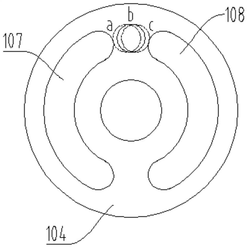
This will cause trapped oil in this area, which will easily cause pressure fluctuations and noise of the pump
[0004] Since the structure of the hydraulic motor has a certain degree of similarity with the axial piston pump, there are also pressure fluctuations and noise problems caused by trapped oil on the hydraulic motor.
[0005] Although some plungers in the prior art can reduce pressure fluctuations and noise problems to a certain extent, they will significantly reduce the efficiency of the plunger pump

Method used


Image

  • A hydraulic pump plunger with small flow pulsation
  • A hydraulic pump plunger with small flow pulsation
  • A hydraulic pump plunger with small flow pulsation

Examples


Embodiment Construction

[0023] The present invention will be further described below in conjunction with accompanying drawing.

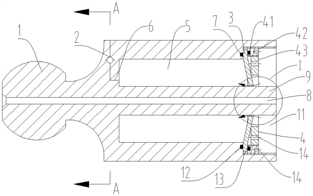
[0024] like Figure 1 to Figure 5 As shown, a plunger for a hydraulic pump with small flow pulsation includes a plunger body 1, and a central through hole 8 penetrating left and right is arranged inside the plunger body 1. The active part is processed with an annular accommodation chamber 5 arranged around the central through hole 8, the opening of the annular accommodation chamber 5 is located on the right end surface of the plunger body 1, and the plunger body 1 is between the annular accommodation chamber 5 and the central through hole 8 The part between them forms a central column 9, and the plunger body 1 is provided with an outwardly expanding annular installation cavity 11 at the right end of the annular accommodation cavity 5; Oil channel 6;

[0025] The inner surface of the annular installation cavity 11 is provided with an internal thread A, and the bottom plane...


PUM


Abstract

A plunger for a hydraulic pump with small flow pulsation. The plunger body is provided with a central through hole and an annular accommodation chamber, a central column is formed between the annular accommodation chamber and the central through hole, and an annular installation chamber is opened at the right end of the annular accommodation chamber. ; The bottom part of the annular installation cavity is sequentially installed with disc springs and fastening rings sleeved on the outside of the central column; the left side of the lower outer edge of the disc spring abuts against the bottom plane of the annular installation cavity, on which There is an annular gap between the inner edge and the outer surface of the center column; the fastening ring includes an outer ring and an inner ring, and the outer ring is installed in the ring-shaped installation cavity through thread fit, and its left end abuts against the lower outer surface of the disc spring. On the rim, the inner ring is installed inside the outer ring through thread fit, and its left end abuts against the outside of the disc spring main body; a check valve is installed in the oil channel opened on the plunger body. The plunger helps to alleviate the oil trapped problem of the plunger pump, can significantly reduce the vibration and noise of the plunger pump, and can ensure the efficiency of the plunger pump.

Description

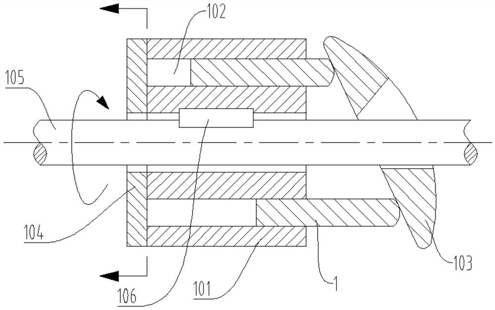
technical field [0001] The invention belongs to the technical field of plunger pump manufacture, in particular to a plunger for a hydraulic pump with small flow pulsation. Background technique [0002] Axial piston hydraulic pump (referred to as axial piston pump) is a hydraulic component that can convert mechanical energy into hydraulic energy. It has many advantages such as high rated working pressure, large flow rate, and convenient variable adjustment. It is widely used in mobile In technical fields such as equipment and fixed equipment. [0003] figure 1 It is a structural principle diagram of a typical axial piston pump in the prior art. In the figure, the cylinder body 101 is arranged with several circular plunger cavities 102 along the axial direction, and the same number of plunger bodies 1 are built in several plunger cavities 102, and one end of the plunger body 1 functions through a suitable method. Keeping in contact with the swash plate 103, the left side of...

Claims


Application Information

Patent Timeline
Patent Type & Authority Patents(China)
IPC IPC(8): F04B53/14F04B53/22F04B53/12F04B11/00F04B1/124F04B1/2014
CPCF04B1/124F04B1/2014F04B11/00F04B11/005F04B53/001F04B53/12F04B53/14F04B53/143F04B53/22
Inventor 李建松许大华周波黎少辉孙金海张文婷
Owner XUZHOU COLLEGE OF INDAL TECH
Learn More