
Anti-impact vibration reduction structure and vibration reduction system for micro-inertia measurement unit

A technology of micro-inertial measurement and vibration-damping structure, which is applied in directions such as navigation through velocity/acceleration measurement, which can solve the problems of large installation space and achieve the effect of simple assembly, good vibration effect, and multiple attenuation.

Active Publication Date: 2020-07-10
SUZHOU R&D CENT OF NO 214 RES INST OF CHINA NORTH IND GRP
View PDF14 Cites 6 Cited by
  • Summary
  • Abstract
  • Description
  • Claims
  • Application Information

AI Technical Summary

Problems solved by technology

This vibration reduction method is applied to the outside of the laser gyro inertial measurement device and relies on the ring connection frame, so it requires a large installation space and is not suitable for the small application installation environment of the micro inertial measurement unit

Method used


Image

  • Anti-impact vibration reduction structure and vibration reduction system for micro-inertia measurement unit
  • Anti-impact vibration reduction structure and vibration reduction system for micro-inertia measurement unit
  • Anti-impact vibration reduction structure and vibration reduction system for micro-inertia measurement unit

Examples


Embodiment 1

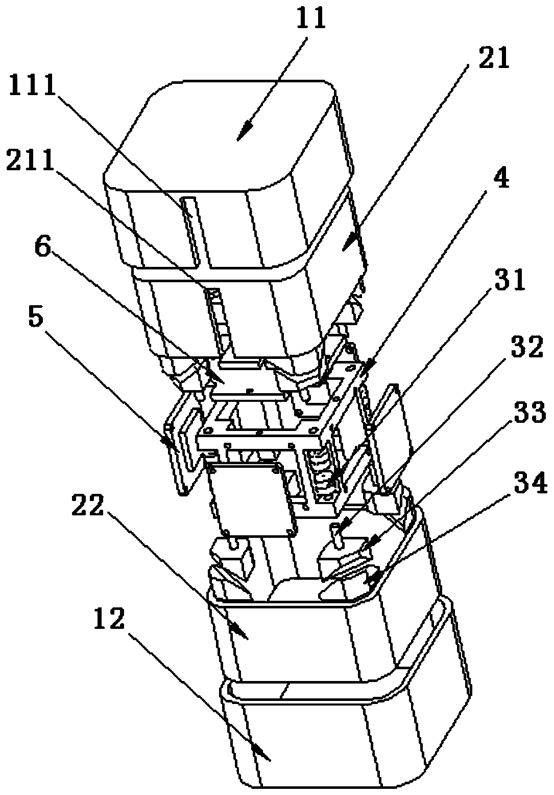
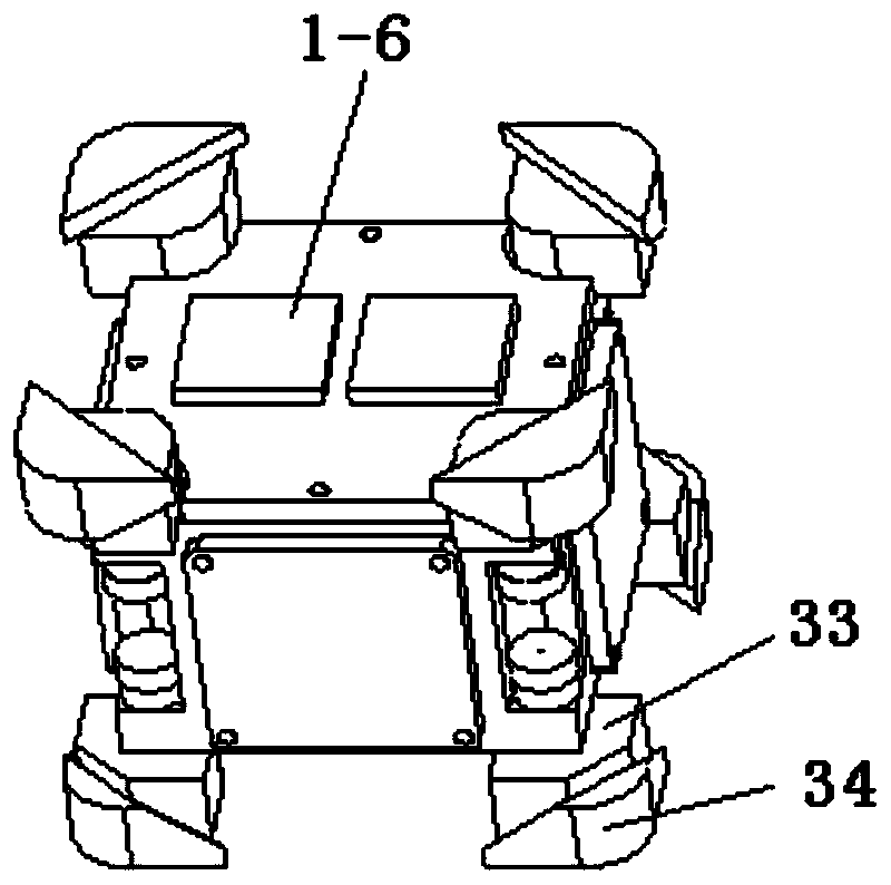
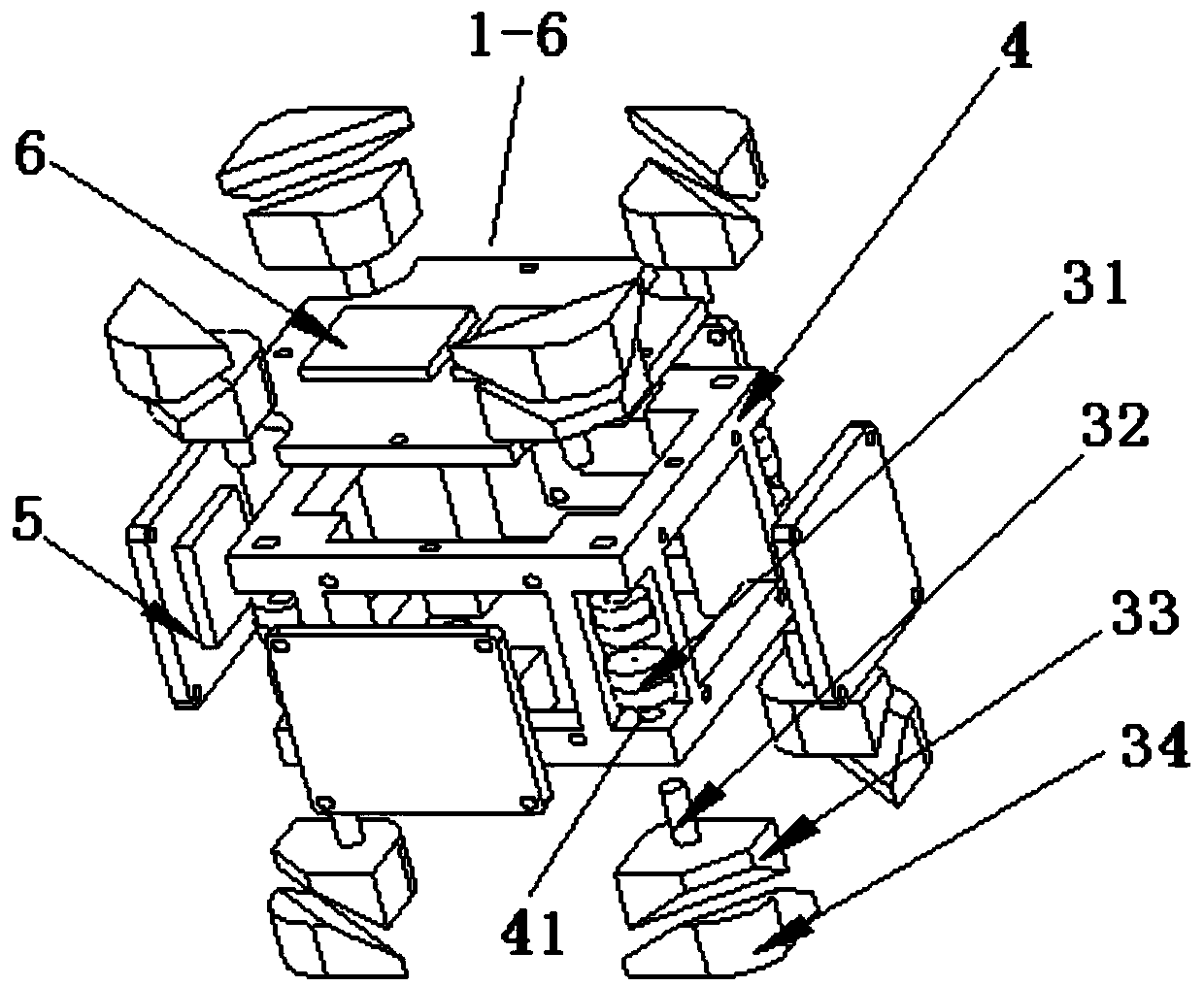
[0066] Such as figure 1 - image 3 As shown, the anti-shock and vibration-damping structure of the micro-inertial measurement unit in this embodiment is used for anti-shock and vibration-damping micro-inertial modules 1-6, including a vibration isolator arranged on a metal support frame 4, a vibration isolator And micro-inertia module 1-6 outside has the metal shell 21,22 that is set up and can accommodate these parts space. The micro-inertial modules 1-6 mainly include a MEMS sensor circuit board 5 and a processor circuit board 6 assembled on a metal support frame 4 .

[0067] In order to realize the inertial parameter measurement of six degrees of freedom, the metal support frame 4 used for assembling the inertial measurement circuit is an approximate hexahedral frame structure to ensure the orthogonality of the measurement coordinate system. The four supporting columns of the hexahedral frame structure are designed to be chamfered inwardly, and the upper top and lower bot...

Embodiment 2

[0071] Such as figure 1 - Figure 4 As shown, on the basis of Embodiment 1, the anti-shock and vibration reduction system of the inertial measurement unit in this embodiment includes: the load-bearing fully-enclosed buffer pads 11, 12 arranged outside the micro-inertial modules 1-6, and the micro-inertia modules 1-6. The inertial modules 1-6 are installed in the base and play a protective impact-resistant protective shell 8 and a cover plate 7 and the like.

[0072] Vibration isolation or attenuation is carried out inside the micro-inertia module, and a load-bearing fully-enclosed buffer pad 11, 12 is respectively set on the two mated metal shells 21, 22 outside the micro-inertia module, so that the micro-inertia module and Measures against high overload impacts are formed between the impact-resistant protective shells 8 .

[0073]The high overload shock that the micro inertial module is concerned about usually occurs during the launch process of the carrier. It is an accele...


PUM


Abstract

The invention discloses a anti-impact vibration reduction structure and a vibration reduction system for a micro-inertia measurement unit, and the structure and system are used for reducing vibrationof a micro-inertia module supported by a supporting frame. The vibration reduction structure comprises a vibration isolator arranged on the supporting frame. The supporting frame is of a hexahedron frame structure, and vibration isolators are arranged at the eight vertex angles of the hexahedron frame structure. Each vibration isolator includes a pair of silicone rubber shock pads which are formedby dividing a dividing surface and are matched with each other. Vibration reduction and impact resistance of the micro-inertia module are achieved in an internal and external combined mode, multipletimes of attenuation of vibration can be achieved, the vibration effect is good, assembling is easy, and the micro-inertia module is suitable for vibration reduction under the condition that the installation space environment is limited.

Description

technical field [0001] The invention relates to an anti-shock and vibration-reduction of an inertial measurement unit, and mainly relates to the field of mechanical structure and buffer vibration-isolation design. Background technique [0002] Micro inertial measurement unit is an inertial measurement system based on MEMS technology. MEMS technology has emerged along with the development of semiconductor integrated circuit micromachining technology and precision mechanical supermachining technology. On the basis of microelectronic technology combined with precision mechanical technology, microsensors, microactuators, micromechanical structures and related signal processing circuits are integrated. In one. Among them, the MEMS inertial device integrates the sensitive microstructure and signal processing circuit through the application of silicon microprocessing technology and highly integrated process technology, and realizes the miniaturization and electromechanical integra...

Claims


Application Information

Patent Timeline
Patent Type & Authority Applications(China)
IPC IPC(8): G01C21/16
CPCG01C21/16
Inventor 蒋鹏
Owner SUZHOU R&D CENT OF NO 214 RES INST OF CHINA NORTH IND GRP
Learn More