Input current detection circuit and method
A technology of voltage detection circuit and input current, applied in the direction of measuring current/voltage, components of electrical measuring instruments, measuring electricity, etc., can solve the problems of adding special power detection chips, high detection cost, large resistance loss, etc. Reliable principle, wide application prospect, simple structure effect
- Summary
- Abstract
- Description
- Claims
- Application Information
AI Technical Summary
Problems solved by technology
Method used
Image

Examples
Embodiment 1
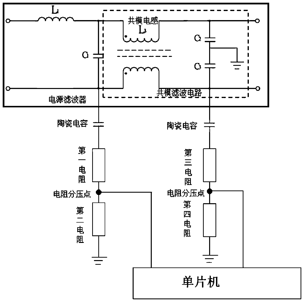
[0040] Such as figure 1 As shown, the embodiment of the present application provides an input current detection circuit, including: a power filter, two ceramic capacitors and a detection circuit. The common mode filter circuit includes two common mode inductors, the coils of the two common mode inductors are wound on the same iron core, and the number of turns of the coils is the same, and the winding directions are opposite; the two ceramic capacitors are only connected to one of them The two ends of the common-mode inductance, the other end of the two ceramic capacitors are connected to the input terminals of the detection circuit; the detection circuit includes two voltage detection circuits and a single-chip microcomputer; one end of the two voltage detection circuits is respectively connected to two ceramic capacitors , the other ends of the two voltage detection circuits are grounded; the voltage detection circuit includes two resistors connected in series; a resistance ...
Embodiment 2
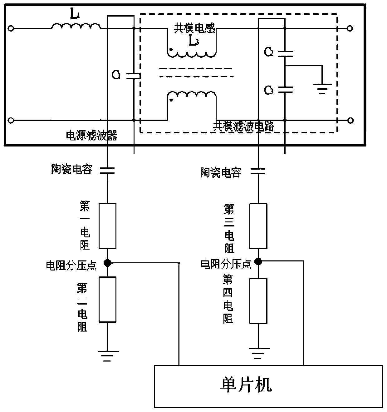
[0050] Such as figure 2 As shown, the embodiment of the present application provides an input current detection circuit. The difference between this embodiment and Embodiment 1 is that two ceramic capacitors are connected to both ends of another common mode inductor. The difference brought about Function effect is the same as embodiment 1.
Embodiment 3
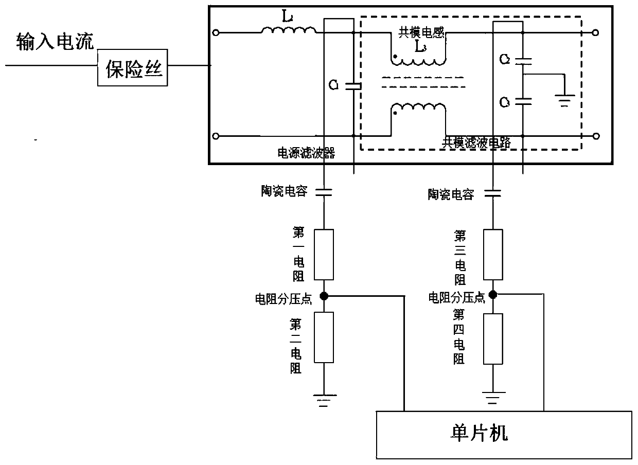
[0052] Such as image 3As shown, the embodiment of the present application provides an input current detection circuit. This embodiment adds a fuse on the basis of Embodiment 1. The fuse is arranged on the line between the external power supply and the power filter. The fuse It protects the input detection circuit.
[0053] Figure 4 is a schematic flowchart of a method in one embodiment of the present invention. in, Figure 4 The execution subject may be an input current detection circuit.
[0054] Such as Figure 4 As shown, the method 100 includes:
[0055] Step 110, collecting the voltages of the two resistor divider points before and after the common mode inductor;
[0056] Step 120, calculating the input voltage and output voltage of the common mode inductor according to the voltage and the resistance value of the line where the resistance voltage dividing point is located;
[0057] Step 130, calculating the difference between the input voltage and the output volt...
PUM
 Abstract
Description
Claims
Application Information
 - R&D
- Intellectual Property
- Life Sciences
- Materials
- Tech Scout
- Unparalleled Data Quality
- Higher Quality Content
- 60% Fewer Hallucinations
Browse by: Latest US Patents, China's latest patents, Technical Efficacy Thesaurus, Application Domain, Technology Topic, Popular Technical Reports.
© 2025 PatSnap. All rights reserved.Legal|Privacy policy|Modern Slavery Act Transparency Statement|Sitemap|About US| Contact US: help@patsnap.com