Bragg period scanning type holographic imager

A holographic imaging and scanning technology, which is applied in the field of 3D imaging, can solve the problems that the visual performance cannot satisfy the user, the 3D picture is not continuous, and the 3D picture cannot be fully realized, so as to improve the viewing experience, protect eyesight, and have no potential safety hazards. Effect

Pending Publication Date: 2020-07-10
JINGMEN CITY DREAM EXPLORATION TECH CO LTD
View PDF5 Cites 1 Cited by
  • Summary
  • Abstract
  • Description
  • Claims
  • Application Information

AI Technical Summary

Problems solved by technology

However, the 3D images formed in this way are not continuous, and the sliced ​​images in the real space cannot completely realize continuous 3D imag

Method used


Image

  • Bragg period scanning type holographic imager
  • Bragg period scanning type holographic imager
  • Bragg period scanning type holographic imager

Examples


Embodiment 1

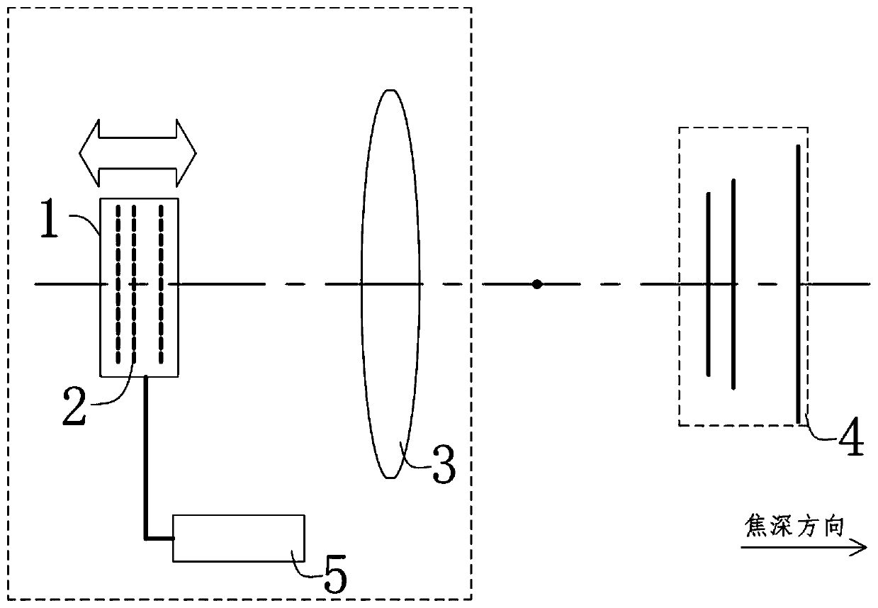
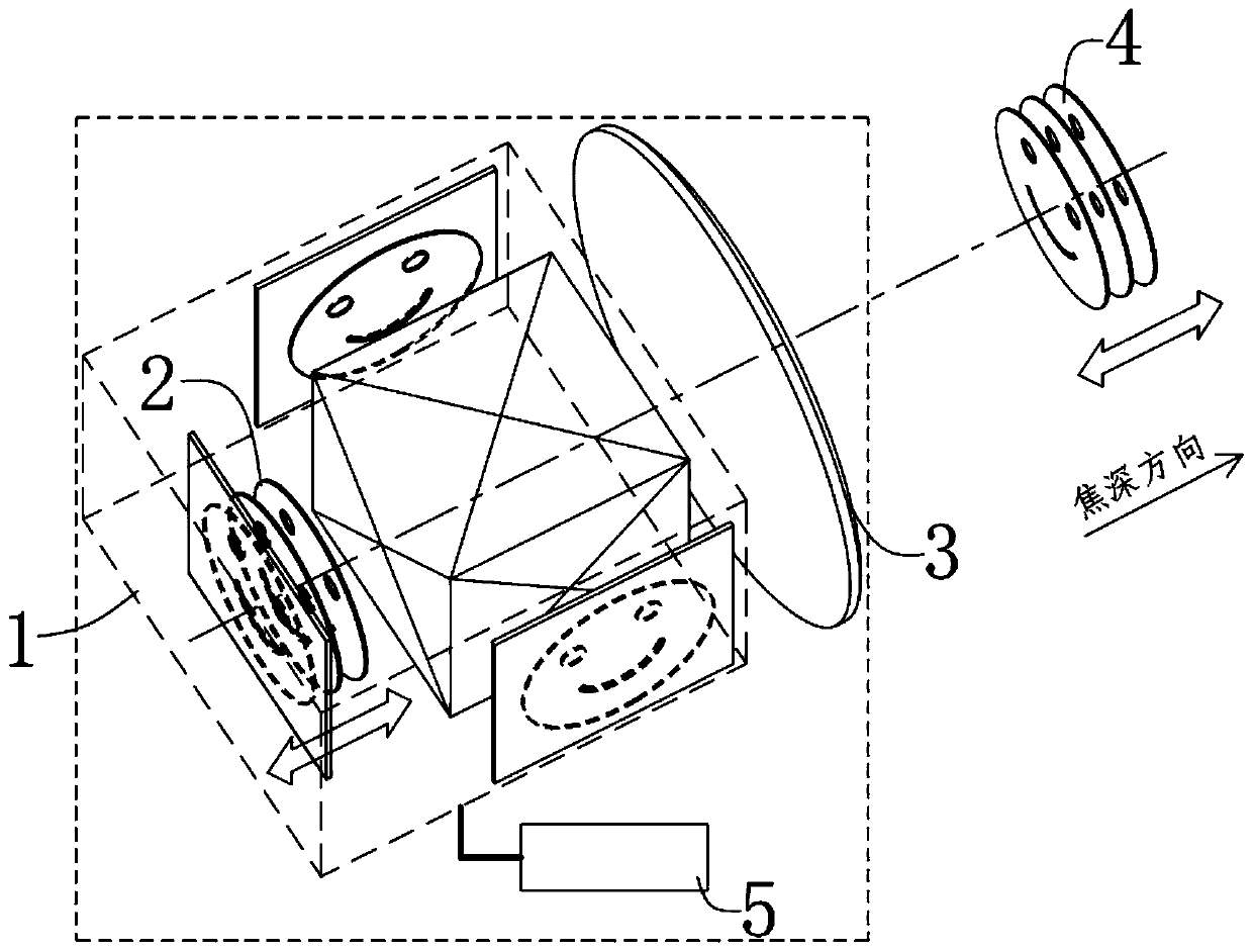
[0056] Such as figure 1 The Bragg periodic scanning holographic imager includes projection display elements, imaging mirrors 3 and focal depth scanning mechanism 5 respectively arranged inside. The focal depth scanning mechanism 5 is connected with the projection display element and controls the projection display element to generate periodicity in the depth of field direction. Back and forth changes, so that the relative position between the equivalent image plane 2 and the imaging lens group 3 also periodically changes, and the two-dimensional cut plane 4 optically conjugated to the equivalent image plane 2 vibrates in the direction of focal depth to perform periodic back and forth Reciprocating scanning to achieve continuous 3D display effect.

Embodiment 2

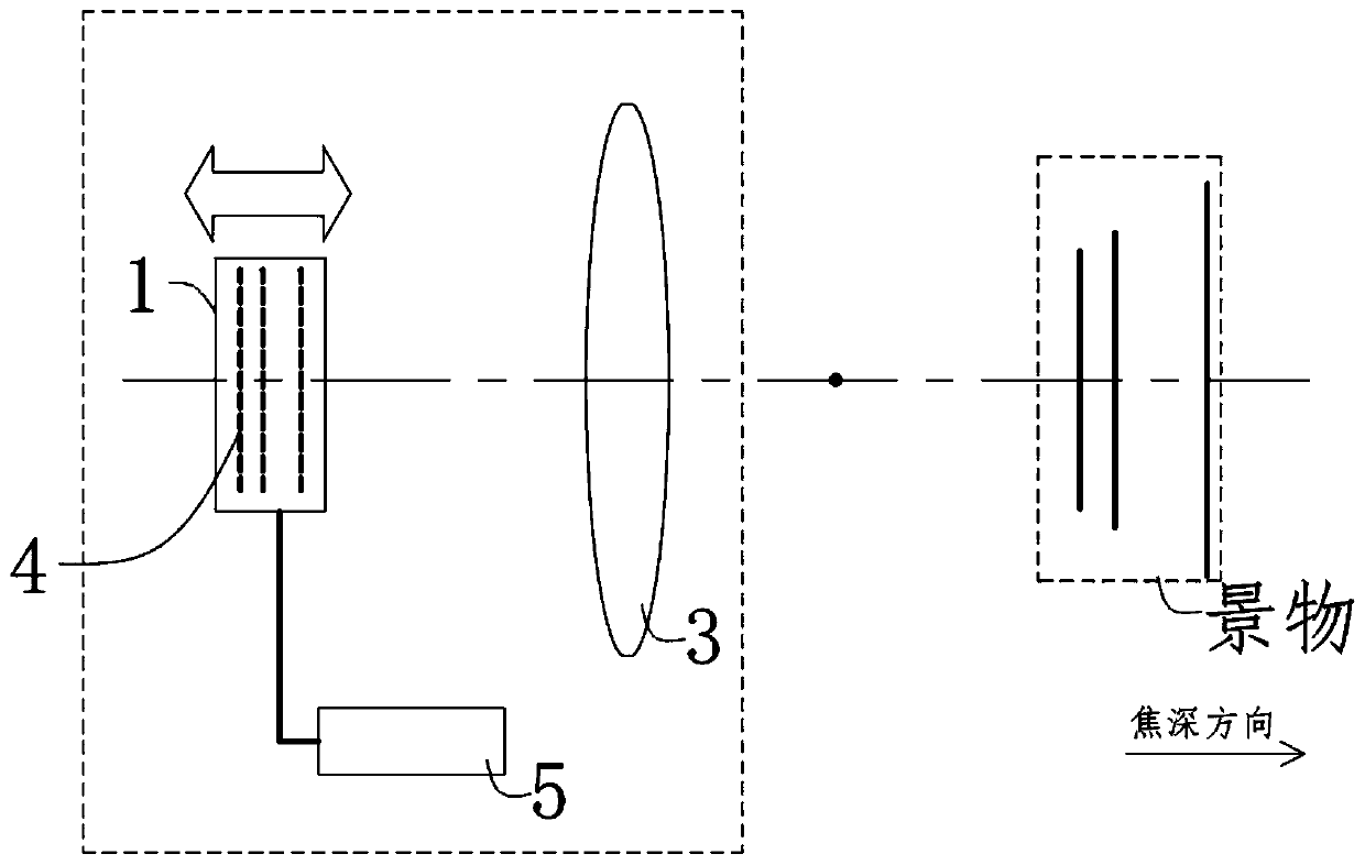
[0058] Such as Figure 5 , the Bragg periodical scanning holographic imager includes a projection display element, an imaging mirror group 3 and a focal depth scanning mechanism 5 respectively arranged inside, and the focal depth scanning mechanism 5 is connected with the imaging mirror group 3 and controls the imaging mirror group 3 to generate Periodic back and forth changes, so that the relative position between the equivalent image plane 2 and the imaging lens group 3 changes periodically, and the two-dimensional cut plane 4 optically conjugated to the equivalent image plane 2 vibrates periodically in the depth of focus direction. Scan back and forth to achieve continuous 3D display effect.

Embodiment 3

[0060] Such as Figure 6 , the Bragg periodic scanning holographic imager includes a projection display element, an imaging mirror group 3, and a focal depth scanning mechanism 5 respectively arranged inside, and the focal depth scanning mechanism 5 is respectively connected with the projection display element and the imaging mirror group 3 and controls the space between them. The position changes back and forth periodically, so that the relative position or the overall position between the equivalent image plane 2 and the imaging lens group 3 changes periodically, and the two-dimensional cut plane 4 optically conjugated to the equivalent image plane 2 is in the direction of the depth of focus Vibration occurs to scan back and forth periodically to achieve a continuous 3D display effect.


PUM


Abstract

The invention relates to the field of 3D imaging. The Bragg period scanning type holographic imager comprises an imaging element, an imaging lens group and a focal depth scanning mechanism which are respectively arranged in the holographic imager, the imaging element is used for providing a plurality of equivalent image planes which are not overlapped or are parallel to one another, and the imaging lens group is used for optical imaging and is provided with a plurality of two-dimensional tangent planes; and the focal depth scanning mechanism is connected with the driving imaging element and/orthe imaging lens group and is used for controlling the spatial position change of the imaging element and/or the imaging lens group to realize volume scanning of the two-dimensional section. According to the invention, a 3D imaging/projection display function with ultra-high resolution and ultra-fast frame frequency can be stably realized by introducing a multi-focal plane and the Bragg period scanning mode.

Description

technical field [0001] The invention relates to the field of 3D imaging, in particular to a Bragg periodic scanning holographic imager. Background technique [0002] 3D display technology can provide additional depth information on the basis of traditional two-dimensional display, so it is considered to be the development direction of next-generation display technology. However, there is no effective solution for realizing 3D display at present, and most of the commercially successful cases are pseudo-3D technologies based on stereoscopic image pairs, which cannot provide users with real 3D images with depth information. For example, the principle of 3D movies in cinemas is to use a projector to project two two-dimensional left and right eye image pairs on the screen. By wearing selective filter eyes, the two eyes receive different images, thus creating a kind of Seeing the illusion of a 3D image, but in fact the projected image is only a 2D image. Prolonged viewing can al...

Claims


Application Information

Patent Timeline
IPC IPC(8): G03B35/18G02B30/56G02B30/54
CPCG03B35/18
Inventor 王广军余为伟
Owner JINGMEN CITY DREAM EXPLORATION TECH CO LTD
Why Eureka
Try Eureka