
Quick locking device for self-locking machine tool part

A locking device and self-locking technology, applied in positioning devices, metal processing mechanical parts, manufacturing tools, etc., can solve the problems of low integration, cumbersome disassembly and assembly process, and many scattered parts.

Active Publication Date: 2020-07-14
湖南九五精机有限责任公司
View PDF11 Cites 1 Cited by
  • Summary
  • Abstract
  • Description
  • Claims
  • Application Information

AI Technical Summary

Problems solved by technology

[0004] Through the research on the above-mentioned invention and the fixture and locking device in the prior art, it is found that people use the slider to slide in the groove to adjust the position, then fix the position with a pin, and finally use fasteners such as bolts for final fastening. This technical solution has the disadvantages of low integration and many scattered parts. At the same time, it also has the problems of cumbersome disassembly and assembly and complicated adjustment stages;

Method used


Image

  • Quick locking device for self-locking machine tool part
  • Quick locking device for self-locking machine tool part
  • Quick locking device for self-locking machine tool part

Examples


Embodiment Construction

[0037] The technical solutions of the present invention will be further specifically described below through the embodiments and in conjunction with the accompanying drawings. In the following description, many specific details are set forth in order to fully understand the present invention, but the present invention can be implemented in many other ways different from those described here, and those skilled in the art can do similar Modifications, and therefore the present invention is not limited to the specific examples disclosed below.

[0038] In the description of the present invention, it should be noted that the orientation or positional relationship indicated by the terms "up", "down", "front", "rear", "left", "right" etc. are based on the Orientation or positional relationship, or the orientation or positional relationship that the inventive product is usually placed in use, is only for the convenience of describing the present invention and simplifying the descript...


PUM


Abstract

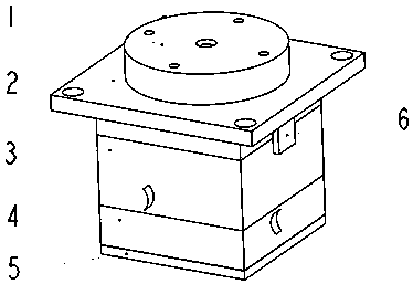
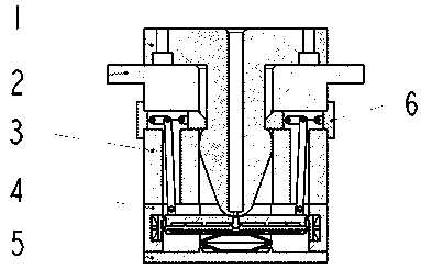
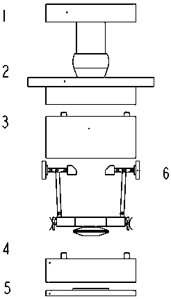
The invention discloses a quick locking device for a self-locking machine tool part. The quick locking device comprises a lock pin, a lock body upper end cover, a lock body upper part, a lock body lower part, a lock body lower end cover and a self-locking mechanism. A pressing plate is driven to be linked in the inserting process of the lock pin, so that a wedge-shaped limiting block of the self-locking mechanism is driven to slide out to achieve automatic locking, meanwhile, the self-locking mechanism reaches a self-locking position at a tail position, and stable locking is achieved. When unlocking is needed, a reset pin is used for pressing the pressing plate to drive the self-locking mechanism to deviate from the self-locking position, and a reset mechanism is triggered to reset after the lock pin is taken out. According to the technical scheme disclosed by the invention, quick positioning and locking are achieved, and the good effect of stable and quick locking is achieved throughthe self-locking characteristic of the mechanism; in addition, the technical scheme of the invention is high in integration level, convenient to operate and simple in configuration.

Description

technical field [0001] The invention relates to the technical field of machine tool automation, in particular to a self-locking fast locking device for machine tool components. Background technique [0002] With the rapid development of manufacturing technology, various multifunctional machine tools and machining centers are becoming more and more popular. The machining center has good versatility and can process various parts. However, due to the different processing techniques of various parts, it is necessary to install various fixtures or other auxiliary processing components on the workbench. In the traditional process, the parts are usually clamped on the workbench by using general fixtures or the operator makes temporary or permanent auxiliary fixtures according to the actual working conditions; [0003] For example, the Chinese utility model patent No.: 201821016723 discloses a universal flexible fixture, which has T-shaped sliding grooves arranged vertically and u...

Claims


Application Information

Patent Timeline
Patent Type & Authority Applications(China)
IPC IPC(8): B23Q3/00
CPCB23Q1/0063B23Q3/06
Inventor 张云朋
Owner 湖南九五精机有限责任公司
Learn More