Spraying device used for building decoration

A spraying device and architectural decoration technology, applied in spraying devices, buildings, devices for coating liquid on surfaces, etc., can solve problems such as long drying time, achieve convenient construction operations, accelerate drying, and avoid complex structures

Active Publication Date: 2020-07-14
CHONGQING VOCATIONAL INST OF ENG
View PDF9 Cites 0 Cited by
  • Summary
  • Abstract
  • Description
  • Claims
  • Application Information

AI Technical Summary

Problems solved by technology

[0003] The purpose of the present invention is to provide a kind of spraying device for architectural decoration, to solve the relatively long drying time after the spraying operation of architectural decoration in the prior art

Method used


Image

  • Spraying device used for building decoration
  • Spraying device used for building decoration

Examples


Embodiment 1

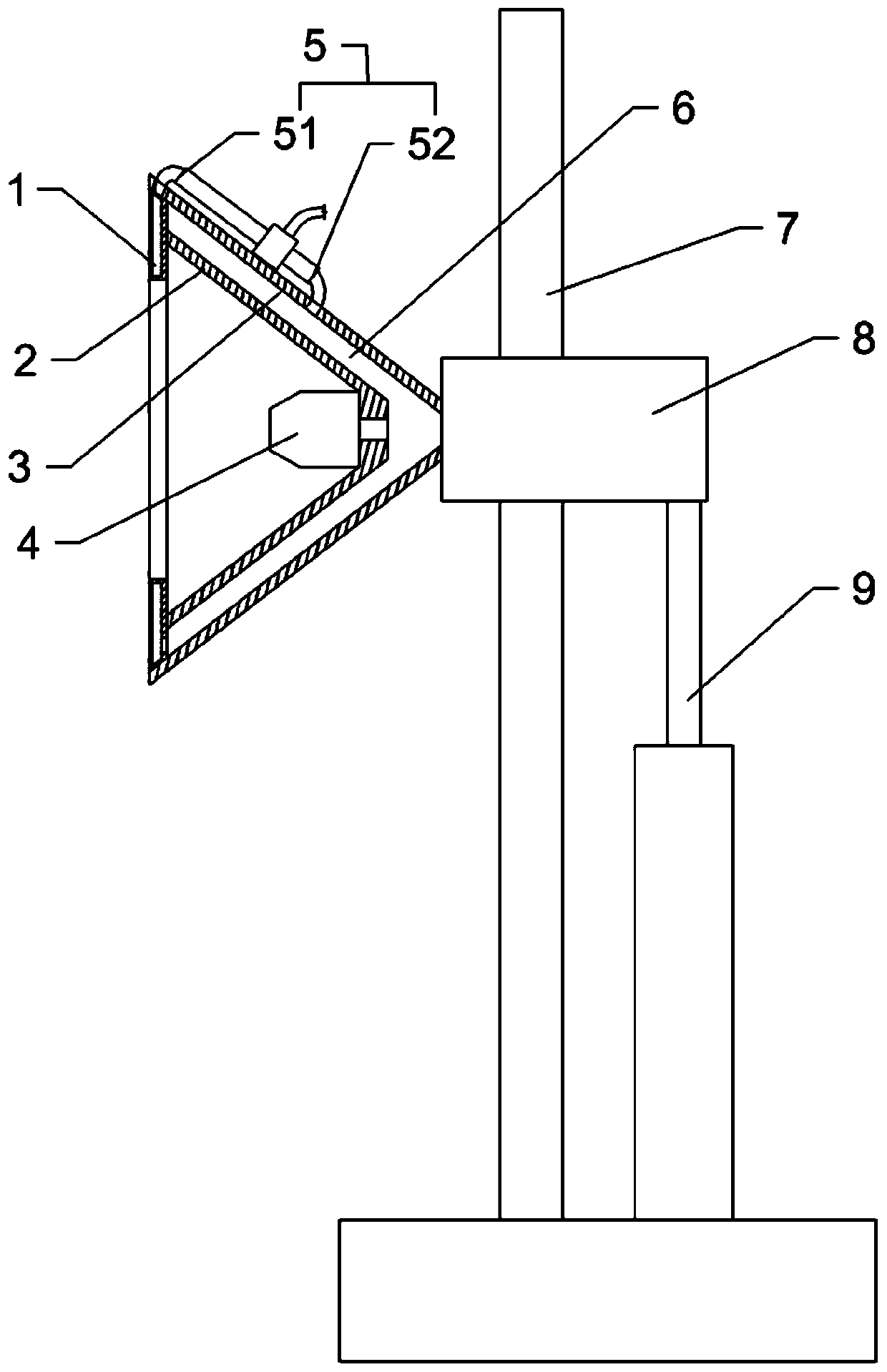
[0019] Embodiment one: if figure 1 Shown: the spraying device for architectural decoration, including a bracket 7, the bottom of the bracket 7 is rotatably connected with rollers for walking, the bracket 7 is vertically slid and connected with a slider 8, between the slider 8 and the bottom of the bracket 7 A telescopic mechanism is connected, and the telescopic mechanism is preferably a cylinder 9 in this embodiment, and the cylinder 9 is arranged vertically, the lower end of the cylinder 9 is hinged with the bottom of the support 7, and the upper end of the cylinder 9 is hinged with the slider 8. The slide block 8 is connected with a spray head 4 whose spraying direction is transverse, and the spray head 4 is connected with a paint supply pipe. The outer side of the nozzle 4 is covered with a first cover 2, the first cover 2 is conical, the axis of the first cover 2 is parallel to the spraying direction of the nozzle 4, the small diameter end of the first cover 2 is in conta...

Embodiment 2

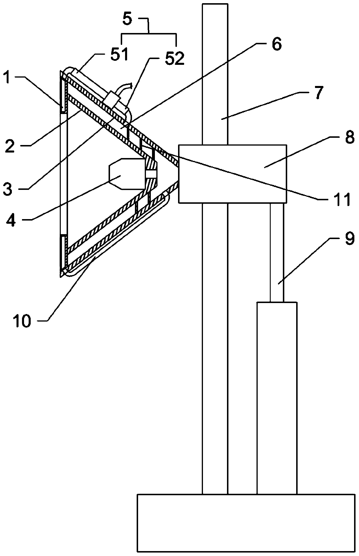
[0022] Embodiment two: the difference with embodiment one is only: as figure 2 As shown, a spiral partition 11 is installed in the cavity 6, the inner edge of the spiral partition 11 is welded and fixed with the first cover body 2, and the outer edge of the spiral partition 11 is against the second cover body 3, so that the spiral partition 11 divides the cavity 6 into a spiral channel; the air outlet of the heat pipe 1 communicates with the position near the nozzle 4 in the cavity 6 through the communication pipe 10, so that the air in the heat pipe 1 can quickly reach the position of the nozzle 4.

[0023] A helical channel is formed in the cavity 6 by the spiral partition 11, so that the cold air discharged from the cold end air outlet 52 of the vortex tube 5 enters the cavity 6 and flows in the helical channel, thus prolonging the cooling time. The flow path in the cavity 6 enables the cold air to exchange heat with the second cover body 3, and the first cover body 2 can ...


PUM


Abstract

The invention belongs to the technical field of appliances of applying plastifying substances to the surface of a building under action of gas pressure in the building decoration project, and particularly relates to a spraying device used for building decoration. The spraying device comprises a bracket, wherein a spray head and an air compression mechanism are connected on the bracket; a first cover body which covers the spray head is connected on the bracket; one end, away from the bracket, of the first cover body is connected to a ring-shaped heat conduction tube; a vortex tube is connectedon the bracket; a gas inlet of the vortex tube communicates with the air compression mechanism; a hot end gas outlet of the vortex tube communicates with a gas inlet end of the heat conduction tube; and a gas outlet end of the heat conduction tube and a cold end gas outlet of the vortex tube communicate with the spray head. According to the scheme adopted by the invention, the spraying device solves the problem that drying time after spraying operation for building decoration in the prior art is relatively long.

Description

technical field [0001] The invention belongs to the technical field of appliances for applying plasticizing substances on building surfaces through the action of air pressure in building decoration engineering, in particular to a spraying device for building decoration. Background technique [0002] In the construction of architectural decoration projects, spraying devices are sometimes used for coloring, and the paint is atomized and sprayed out by using air with a certain pressure, so that the paint is evenly attached to the building. After the spraying operation is completed, it is necessary to wait for the paint to dry before proceeding to the next process, which affects the progress of the entire decoration construction. How to shorten the time required for drying after spraying is an urgent problem to be solved now. Contents of the invention [0003] The object of the present invention is to provide a spraying device for architectural decoration, so as to solve the ...

Claims


Application Information

Patent Timeline
IPC IPC(8): E04F21/12B05D3/02B05B14/00B05B15/68
CPCB05D3/0254B05B14/00B05B15/68E04F21/12
Inventor 邹松夏
Owner CHONGQING VOCATIONAL INST OF ENG
Why Eureka
Try Eureka