Flue gas waste heat recovery device and method with spark capturing function

A flue gas waste heat and recovery device technology, which is applied in the field of high-temperature flue gas treatment in the metal melting process, can solve problems such as easy fires, and achieve the effects of improving resource utilization, improving equipment utilization, and realizing energy saving.

Pending Publication Date: 2020-07-14
QINHUANGDAO ZHONGQIN BOHAI HUB CO LTD
View PDF0 Cites 0 Cited by
  • Summary
  • Abstract
  • Description
  • Claims
  • Application Information

AI Technical Summary

Problems solved by technology

[0004] The purpose of the present invention is to provide a flue gas waste heat recovery device with the function of a spark catcher to solve the problem of easy fires in the proces

Method used


Image

  • Flue gas waste heat recovery device and method with spark capturing function
  • Flue gas waste heat recovery device and method with spark capturing function
  • Flue gas waste heat recovery device and method with spark capturing function

Examples


Embodiment 1

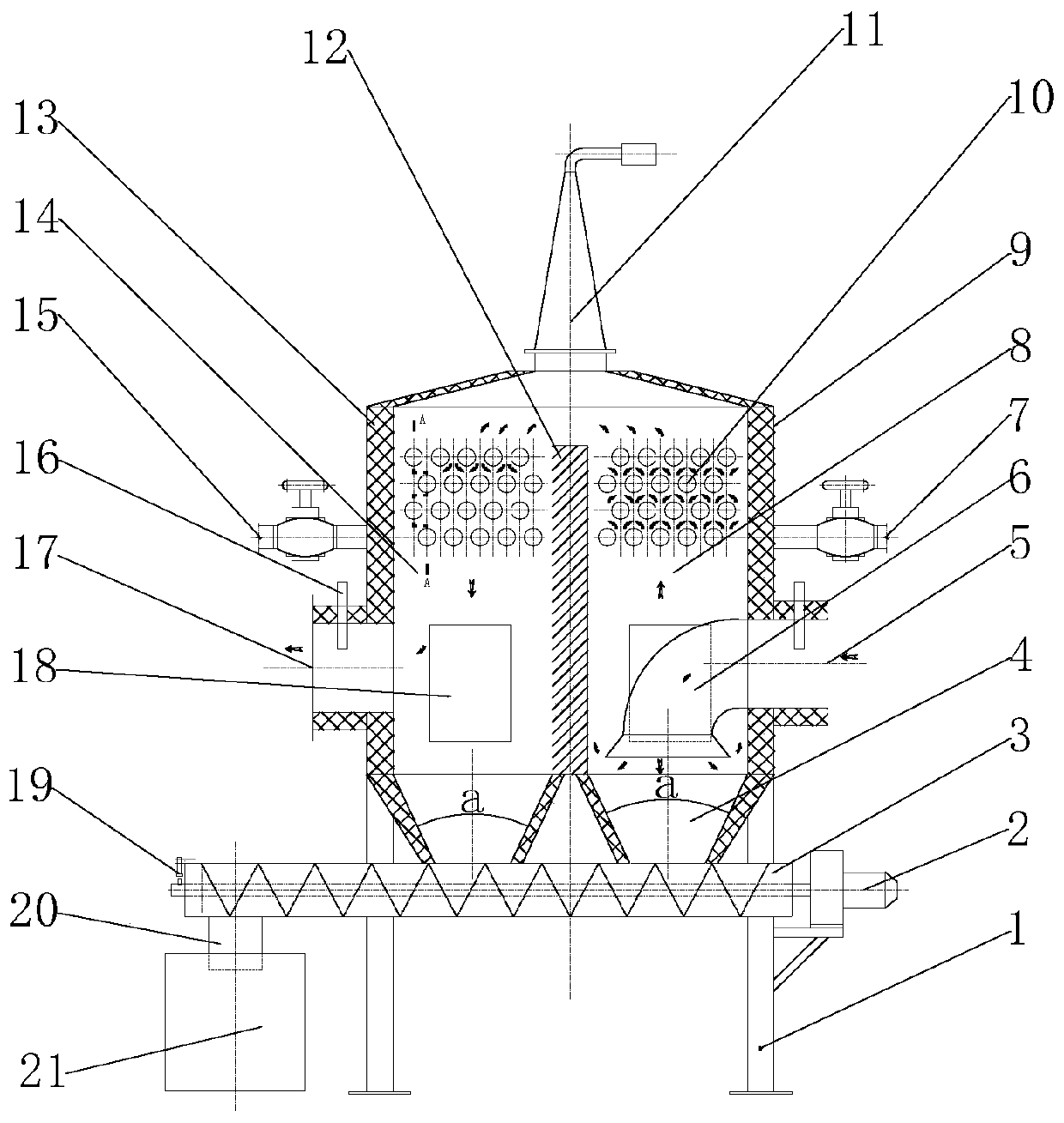
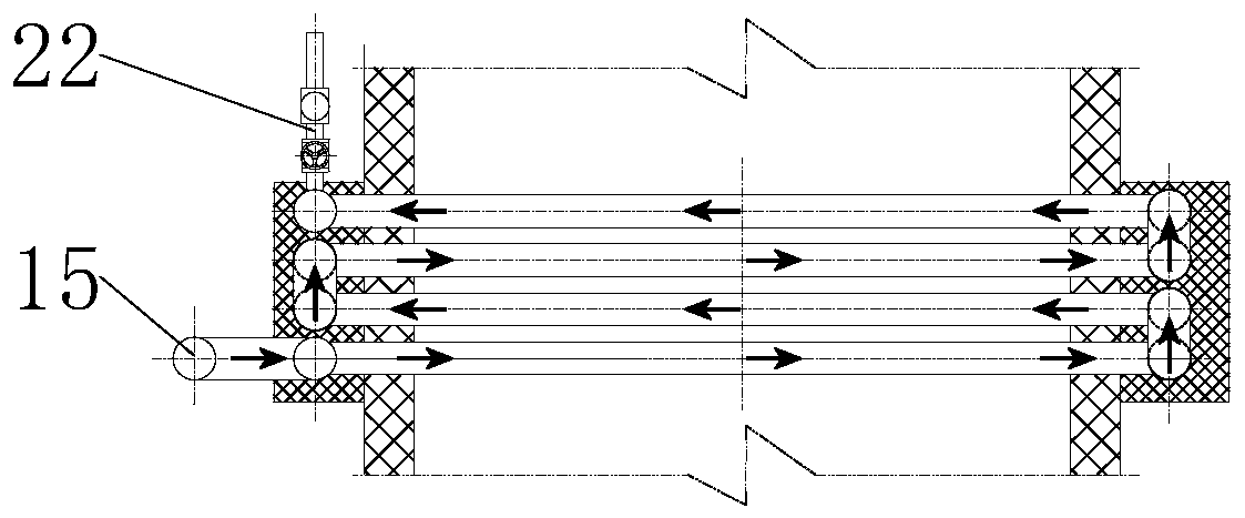
[0031] like Figure 1 to Figure 2 As shown, the flue gas waste heat recovery device with spark capture function of the present invention includes a frame 1 and a box body 9 installed on the frame 1, a soot blower 11 is installed on the top of the box body 9, and a soot blower 11 is installed in the box body 9 The partition 12 divides the box body into a left chamber 14 and a right chamber 8, and the lower ends of the left and right sides of the box body 9 are provided with a smoke outlet 17 and a smoke inlet 5 to communicate with the left chamber 14 and the right chamber 8 respectively. , the box body 9 is provided with an elbow 6 connected to the flue gas inlet 5, and the left and right chambers are provided with a column pipe 10 with a spark capture function connected to the water supply pipe 15 and the drain pipe 7 outside the box body 1, and the bottom of the box body 9 The ash discharge hopper 4 connected with the left and right chambers is symmetrically arranged, the ash...

Embodiment 2

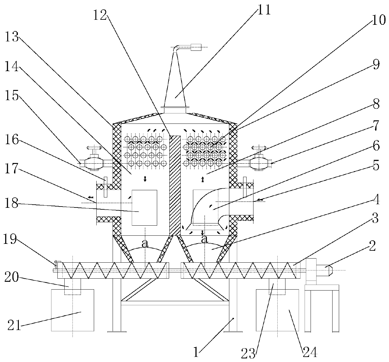
[0042] like image 3 As shown, the difference between the flue gas waste heat recovery device with spark capture function in this embodiment and that in Embodiment 1 is that the conveyor 3 connected to the ash discharge hopper 4 has a coaxial two-stage structure, and the two stages rotate in opposite directions. It is connected with the left and right chamber ash discharge hoppers 4, the lower side of the outer end of one section is connected with the first ash discharge port 20, the first collection box 21 is arranged on the lower side of the first ash discharge port 20, and the outer end of the other section The lower side is connected with the second ash discharge port 23, and the second collection box 24 is arranged on the lower side of the second ash discharge port 23. The conveyor 3 is driven by the motor 2, and the dust particles etc. falling from the left chamber 14 pass through the second collection box 24. A row of ash outlets 20 are discharged to the first collectio...


PUM


Abstract

The invention relates to the technical field of high-temperature flue gas treatment in the metal melting process, in particular to a flue gas waste heat recovery device and method with a spark capturing function. The flue gas waste heat recovery device and method solve the problem that a fire is prone to being caused in the flue gas waste heat recovery process, the particulate matter treatment difficulty is lowered, the resource utilization rate is increased, and the cost is reduced. The device adopts the spark capturing and waste heat recovery integrated design and comprises a rack and a boxbody mounted on the rack. A soot blower is mounted at the top of the box body. A partition plate mounted in the box body divides the box body into a left chamber and a right chamber. A flue gas outletand a flue gas inlet are formed in the lower ends of the left side and the right side of the box body and communicate with the left chamber and the right chamber correspondingly. A bent pipe connected with the flue gas inlet is arranged in the right chamber. The left chamber and the right chamber are each provided with a tube nest with the spark capturing function. The tube nests are connected with a water supply pipe and a water drainage pipe on the outer side of the box body correspondingly. Ash discharging hoppers communicating with the left chamber and the right chamber are symmetricallyarranged at the bottom of the box body. The lower ends of the ash discharging hoppers are connected with a conveying device.

Description

technical field [0001] The invention relates to the technical field of high-temperature flue gas treatment in the metal melting process, in particular to a flue gas waste heat recovery device and method with spark capture function. Background technique [0002] In the production of metal melting process, a large amount of smoke and dust will be produced. In order to reduce pollution, bag type dust collector is usually used to separate the dust, reduce the emission of dust particles, and meet the needs of the environment. Dust and particles such as sparks are entrained in the flue gas. In order to prevent sparks from entering the bag filter, a spark arrestor is usually installed on the inlet pipe of the bag filter to eliminate potential safety hazards. [0003] Existing Mars capture devices focus on the function of capturing Mars and reducing the temperature of the flue gas. However, the flue gas dust particles generated during the metal melting process are usually viscous an...

Claims


Application Information

Patent Timeline
IPC IPC(8): F27D17/00F23J3/00A62C3/00B01D53/00B01D53/26B01D45/02B01D45/08
CPCA62C3/00B01D45/02B01D45/08B01D53/002B01D53/265B01D2258/0283F23J3/00F27D17/004F27D17/008Y02P10/25
Inventor 李玉栓钱炜麟张殿杰
Owner QINHUANGDAO ZHONGQIN BOHAI HUB CO LTD
Why Eureka
Try Eureka