Telescope diopter focusing structure

A telescope and diopter technology, which is applied in the field of telescope diopter focusing structure, can solve problems such as complex structure, complicated focusing structure, and changes, and achieve the effect of high controllability, convenient and fast focusing

Pending Publication Date: 2020-07-14
成都赛诺特光学有限公司
View PDF0 Cites 0 Cited by
  • Summary
  • Abstract
  • Description
  • Claims
  • Application Information

AI Technical Summary

Problems solved by technology

[0002] The traditional binoculars usually need to adjust the focal length by setting the handwheel and the corresponding connection structure. The existence of the handwheel and its connection structure makes the whole focusing structure more complicated. In the state of the connection of the mirror frame, once the handwheel is touched when using the telescope, it may drive the eyepiece frame to move and cause the misoperation of the focus to change
Therefore, in view of the defects of the traditional lens barrel focusing structure, such as complex structure, large volume, and prone to misoperation caused by touch, the present invention discloses a telescope diopter focusing structure

Method used


Image

  • Telescope diopter focusing structure
  • Telescope diopter focusing structure
  • Telescope diopter focusing structure

Examples


Embodiment 1

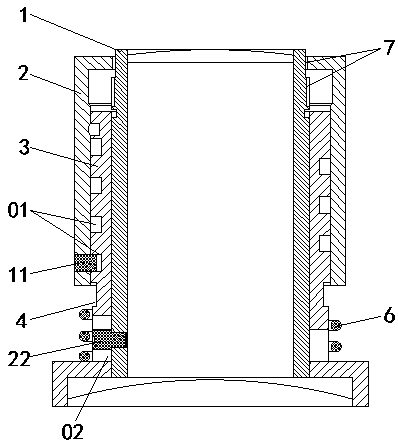
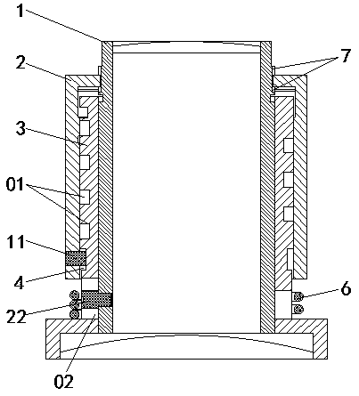
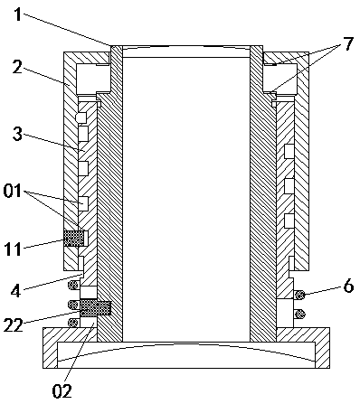
[0049] A telescope diopter focusing structure of this embodiment, such as Figure 1-Figure 17 As shown, it includes a fixed eyepiece seat 3, the outer side of the eyepiece seat 3 is coaxially provided with a movable eyecup 2 that is axially movable relative to the eyepiece seat 3, and the inner side of the eyepiece seat 3 is coaxially provided with a movable eyecup relative to the eyepiece seat. 3 Axially movable eyepiece frame 1; an avoidance ring groove 4 for limiting the axial movement of the movable eyecup 2 is provided between the eyepiece seat 3 and the movable eyecup 2, and between the movable eyecup 2 and the eyepiece frame 1 A movable engaging part 7 that is connected or disconnected with the axial movement of the movable eye mask 2 is provided.

[0050] The outer bottom of the eyepiece seat 3 is provided with an avoidance ring groove 4 along the circumferential direction, and the outer coaxial movable sleeve of the eyepiece seat 3 is equipped with a movable goggle 2,...

Embodiment 2

[0055] This embodiment is further optimized on the basis of Embodiment 1, and the connection modes between the eyepiece holder 3 and the movable eye mask 2 include the following three types:

[0056] (A1) The eyepiece seat 3 and the movable eyecup 2 are movably connected through a spiral groove and a pin screw, that is, a spiral groove is set on any structure of the eyepiece seat 3 or the movable eyecup 2, and an extension is set on the other structure. a pin that goes inside the helical groove and turns helically along the helical groove;

[0057] (A2) The eyepiece seat 3 and the movable eyecup 2 are directly threaded through a multi-start thread, that is, a long multi-start thread is set on any structure of the eyepiece seat 3 or the movable goggle 2, and one end of the long multi-start thread is connected to the escape ring groove. 4 is connected, and the short multi-start thread that is threadedly connected with the long multi-start thread is arranged on another structure;...

Embodiment 3

[0070] This embodiment is further optimized on the basis of Embodiment 1. The connection mode between the eyepiece seat 3 and the eyepiece frame 2 adopts A1, the connection mode between the eyepiece seat 3 and the eyepiece frame 1 adopts B1, and the connection mode between the eyepiece seat 3 and the eyepiece frame 1 adopts B1. The clamping structure of the movable clamping part 7 between 1 adopts C2, and the specific connection structure is as follows:

[0071] A first helical groove 01 is provided on the outer surface of the eyepiece holder 3, and an escape ring groove 4 communicating with the bottom end of the first helical groove 01 is provided at the bottom of the outer surface of the eyepiece holder 3, and is penetrated on the movable eye mask 2 There is a first pin 11 that extends to the inside of the first helical groove 01 and slides helically along the first helical groove 01; a second helical groove 02 is provided through the bottom of the eyepiece holder 3, and a se...


PUM


Abstract

The invention discloses a telescope diopter focusing structure, which comprises a fixedly-arranged eyepiece seat. A movable eyeshade which axially moves relative to the eyepiece seat is coaxially arranged on the outer side of the eyepiece seat, and an eyepiece frame which axially moves relative to the eyepiece seat is coaxially arranged on the inner side of the eyepiece seat. An avoiding annular groove for limiting the axial movement of the movable eyeshade is formed between the eyepiece seat and the movable eyeshade; a movable clamping part connected or disconnected along with the axial movement of the movable eyeshade is arranged between the movable eyeshade and the eyepiece frame. On the premise that a hand wheel and a connecting structure of the hand wheel are not arranged, the focusing structure is simpler and more compact, meanwhile, convenient and rapid focusing is achieved, and meanwhile focusing misoperation caused by touch is effectively avoided.

Description

technical field [0001] The invention belongs to the technical field of focus adjustment devices, and in particular relates to a telescope diopter focus adjustment structure. Background technique [0002] The traditional binoculars usually need to adjust the focal length by setting the handwheel and the corresponding connection structure. The existence of the handwheel and its connection structure makes the whole focusing structure more complicated. In the state of the connection of the mirror frame, once the handwheel is touched when using the telescope, it may drive the eyepiece frame to move and cause a misoperation of changing the focus. Therefore, the present invention discloses a telescope diopter focusing structure, aiming at the defects of complex structure, large volume and prone to misoperation caused by touch in the traditional lens barrel focusing structure. Contents of the invention [0003] The object of the present invention is to provide a telescope diopter...

Claims


Application Information

Patent Timeline
Patent Type & Authority Applications(China)
IPC IPC(8): G02B7/06G02B23/16G02B25/00
CPCG02B7/06G02B23/16G02B25/001
Inventor 梁广渠张富贵
Owner 成都赛诺特光学有限公司
Why Eureka
Try Eureka