
A high voltage DC contactor

A high-voltage DC, contactor technology, applied in relays, electromagnetic relays, electromagnetic relay details and other directions, can solve the problems of concentrated bias direction and low degree of deviation of arc direction, to improve the degree of deviation, enhance anti-ablation, Enhance the effect of the magnetic field

Active Publication Date: 2022-05-20
CHINA AEROSPACE TIMES ELECTRONICS CORP
View PDF10 Cites 0 Cited by
  • Summary
  • Abstract
  • Description
  • Claims
  • Application Information

AI Technical Summary

Problems solved by technology

[0004] The technical problem of the present invention is to overcome the deficiencies of the existing technology and provide a high-voltage DC contactor, which overcomes the problems of low arc direction deviation and concentrated bias direction caused by the design of the magnetic field distribution of the arc extinguishing system of the existing high-voltage DC contactor , reducing the ablation of the arc on the contacts of the contactor, prolonging the service life of the high-voltage DC contactor

Method used


Image

  • A high voltage DC contactor
  • A high voltage DC contactor

Examples


Embodiment 1

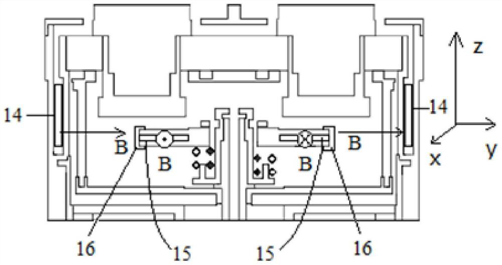
[0033] The nature of the arc is charged particles. When a charged particle is subjected to a magnetic field that is not parallel to the direction of motion, it will be affected by the Lorentz force: Among them, q represents the electric charge of the charged particle, represents the velocity of the charged particle, Indicates the magnetic field (magnetic induction) experienced by charged particles. When the discharge arc is subjected to the Lorentz force, the arc will deviate from the original trajectory. After deviating from the original track, the arc is twisted into a spiral shape, and finally the arc ablation site is no longer concentrated in a certain area on the contact, but tends to be evenly distributed, thereby achieving the effect of improving the electrical life.

[0034] Because electrons are affected by the magnetic field component of the Lorentz force in the direction perpendicular to the direction of motion, they move in a circle. The radius R of circular...

Embodiment 2

[0045] On the basis of the above-mentioned embodiments. The following describes in detail in conjunction with a specific example.

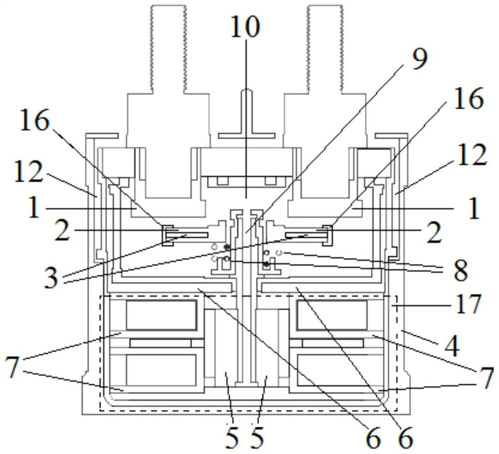
[0046] First, the moving contact magnet 15 is placed in the moving contact magnet groove 3 inside the moving contact 2, and the moving contact magnet sleeve 16 is installed on the outside of the moving contact 2; the static contact The magnetic steel 14 is placed in the static contact magnetic steel groove 12 located on both sides outside the arc extinguishing chamber 10; one end of the magnetic driving rod 9 extending into the arc extinguishing chamber 10 is connected with the magnetic moving contact 2, and the other end passes through After the yoke 6, it is connected with the magnetic drive mechanism 17 through the armature 5. At the same time, the reset coil 7 is placed between the yoke 6 and the armature 5, on both sides of the magnetic drive mechanism 17, and the spring 8 is wound around the magnetic force. on the driving rod 9; so far, the...


PUM


Abstract

The invention discloses a high-voltage direct current contactor, comprising: a casing, two static contacts, a moving contact, an armature, a yoke, a reset coil, a spring, a magnetic drive rod, an arc extinguishing chamber and a Magnetic drive mechanism; the arc extinguishing chamber is located above the inner cavity of the casing, and the magnetic drive mechanism is located at the bottom of the inner cavity of the casing; two static contacts are symmetrically arranged on both sides of the arc extinguishing chamber cavity; the magnetic drive rod is vertically arranged at the centerline of the casing ; Among them, one end of the magnetic drive rod extending into the arc extinguishing chamber is connected with the magnetic movable contact, and the other end passes through the yoke, and is connected with the magnetic drive mechanism through the armature; the reset coil is arranged between the yoke and the armature and is located in the magnetic drive mechanism. Both sides of the mechanism; the spring wraps around the magnetic drive rod. The invention overcomes the problems of low arc direction deviation and concentrated bias direction caused by the magnetic field distribution of the existing high-voltage direct-current contactor arc extinguishing system design, reduces the ablation of the contactor by the arc, and prolongs the life of the high-voltage direct-current contactor. service life.

Description

technical field [0001] The invention belongs to the technical field of electronic components, in particular to a high-voltage DC contactor. Background technique [0002] With social development and scientific and technological progress, informatization, integration, and intelligence continue to deepen, industries such as aerospace, weapon systems, and transportation have higher and higher requirements for the voltage, power, and reliability of power systems. High-power DC power supply is considered to be an inevitable trend of power supply and distribution for future spacecraft, weaponry, rail transit, and automobiles due to its high performance, high reliability, and high efficiency. As the core device in the high-voltage DC power distribution system, the high-power high-voltage DC contactor is of great importance in its performance and reliability. [0003] During the closing and opening process of the contactor, arc discharge inevitably occurs between the moving and stat...

Claims


Application Information

Patent Timeline
Patent Type & Authority Patents(China)
IPC IPC(8): H01H50/38H01H50/18H01H50/54H01H50/56H01H50/04
CPCH01H50/38H01H50/18H01H50/54H01H50/56H01H50/04
Inventor 赵鑫苌群峰冯萃峰田亚伟张楚贤郑国龙
Owner CHINA AEROSPACE TIMES ELECTRONICS CORP
Learn More