
Load structure and radio frequency amplifier formed by same

A technology of radio frequency amplifier and load structure, which is applied in the field of communication and can solve problems such as difficulty in meeting the gain

Pending Publication Date: 2020-07-14
杭州易百德微电子有限公司
View PDF25 Cites 0 Cited by
  • Summary
  • Abstract
  • Description
  • Claims
  • Application Information

AI Technical Summary

Problems solved by technology

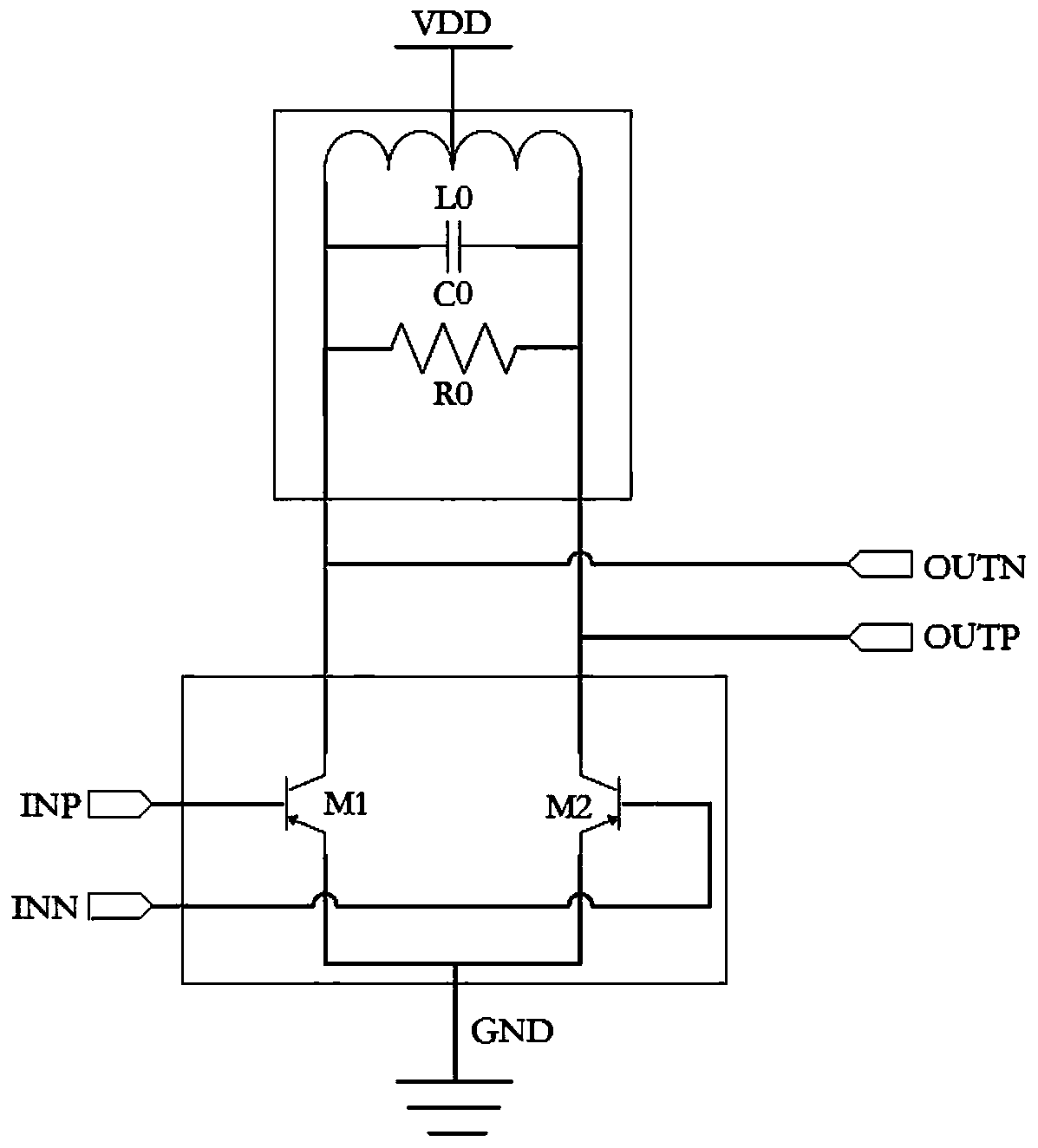
In the design of radio frequency amplifiers in the prior art, single-stage RLC parallel resonant network is mostly used as the load, but single-stage RLC parallel resonant network is a narrow-band system, which is difficult to meet the requirements for gain, bandwidth and gain flatness. e.g. UWB communication system

Method used


Image

  • Load structure and radio frequency amplifier formed by same
  • Load structure and radio frequency amplifier formed by same
  • Load structure and radio frequency amplifier formed by same

Examples


no. 1 example

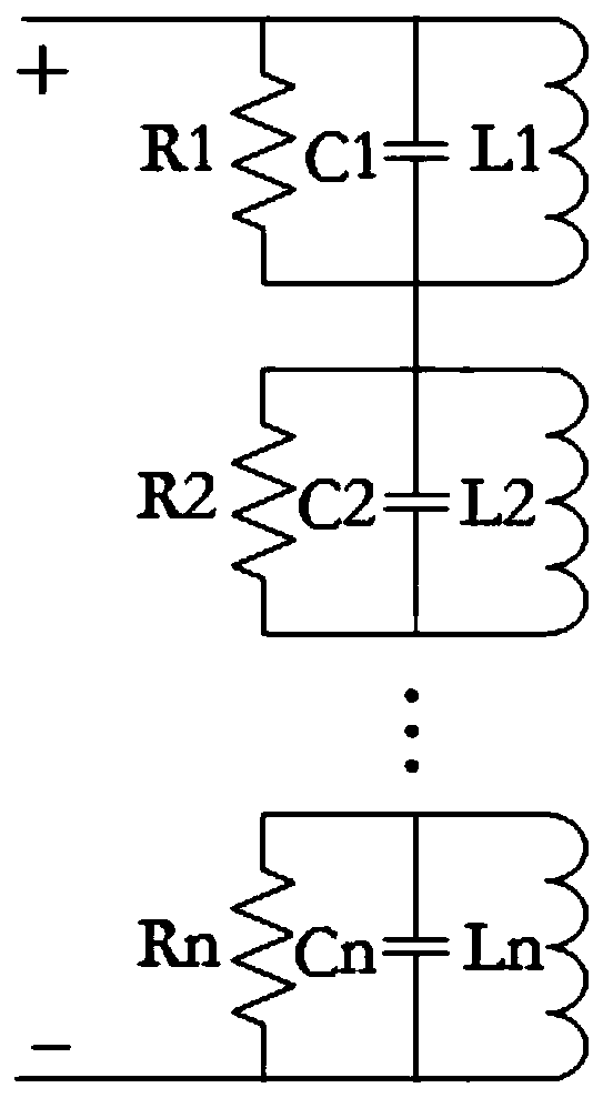
[0054] Such as Figure 6 As shown, the present invention provides a first embodiment of a load structure for a radio frequency amplifier, including:

[0055] N parallel RLC circuits in series, the first connection end of the first parallel RLC circuit is used as the first connection end A of the load structure, and the second connection end of the Nth parallel RLC circuit is used as the load structure. The second connection terminal B, the The second connection end of a parallel RLC circuit (that is, the first The first connecting end of a parallel RLC circuit) is connected to the power supply voltage VDD;

[0056] Among them, the parameters of the Mth parallel RLC circuit device and the (N-M+1)th parallel RLC circuit device constitute a first-level RLC parallel resonant network, and the parameters of the same device in the RLC parallel resonant network at the same level are the same, the load structure have Level RLC parallel resonant network, N is a multiple of 2, N>M...

no. 2 example

[0061] Such as Figure 7 As shown, the present invention provides a second embodiment of a load structure for a radio frequency amplifier, comprising:

[0062] N parallel RLC circuits connected in series in sequence, the first connection end of the first parallel RLC circuit is used as the first connection end of the load structure, and the second connection end of the Nth parallel RLC circuit is used as the first connection end of the load structure Two connections, the The second connecting end of the parallel RLC circuit is connected to the power supply voltage VDD;

[0063] Among them, the parameters of the Mth parallel RLC circuit device and the (N-M+1)th parallel RLC circuit device constitute a first-level RLC parallel resonant network, and the parameters of the same device in the RLC parallel resonant network at the same level are the same, the load structure have Level RLC parallel resonant network, N is a multiple of 2, N>M. In actual design, considering design ...


PUM


Abstract

The invention discloses a load structure for a radio frequency amplifier. The load structure comprises N parallel type RLC circuits which are sequentially connected in series, the first connecting endof the first parallel type RLC circuit is used as the first connecting end of the load structure, the second connecting end of the Nth parallel type RLC circuit is used as the second connecting end of the load structure, and the second connecting end of the Nth parallel type RLC circuit is connected with a power supply voltage; the Mth parallel RLC circuit device parameter and the (N-M + 1)th parallel RLC circuit device form a first-stage RLC parallel resonance network, the same device parameters in the same-stage RLC parallel resonance network are the same, the load structure has the same-stage RLC parallel resonance network, N is a multiple of 2, and N is greater than M. Compared with the technology of the prior art, the load structure and the radio frequency amplifier formed by the load structure provided by the invention have the advantages that voltage gain can be increased by at least 4.4 dB to 6.3 dB, or bandwidth can be increased by at least 2.5 times and gain flatness can beincreased by at least 2.6 times under the same gain.

Description

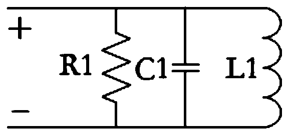
technical field [0001] The invention relates to the communication field, in particular to a load structure used for a radio frequency amplifier. The invention also relates to a radio frequency amplifier composed of the load structure. Background technique [0002] RF amplifiers are essential modules in RF chip design, such as low noise amplifiers in receivers, power amplifiers in transmitters, etc. The RF amplifier can be divided into two parts: the active amplifier tube and the load. The active amplifier tube may be MOSFET or BJT according to the process. The load part is responsible for providing a certain impedance. Most of the current technologies use a single-stage RLC parallel resonant network, such as figure 1 shown. [0003] Gain, bandwidth and gain flatness are one of the most important indicators of RF amplifiers. According to different application scenarios, the RF system will put forward corresponding index requirements for gain, bandwidth and gain flatness. ...

Claims


Application Information

Patent Timeline
Patent Type & Authority Applications(China)
IPC IPC(8): H03F3/189
CPCH03F3/189
Inventor 刘磊
Owner 杭州易百德微电子有限公司
Learn More