Patient body position adjusting device for scanning of medical CT machine

An adjustment device and body position technology, applied in the field of medical equipment, can solve problems such as poor automatic adjustment ability, difficulty in supporting placement, inconvenience, etc., and achieve the effects of high degree of automation, convenient adjustment of patient's body position, and high use value

Inactive Publication Date: 2020-07-17
THE SECOND AFFILIATED HOSPITAL OF SHANDONG FIRST MEDICAL UNIV
View PDF1 Cites 2 Cited by
  • Summary
  • Abstract
  • Description
  • Claims
  • Application Information

AI Technical Summary

Problems solved by technology

When the adjustment device is in use, since only the upper side of the turnover plate is provided with grooves, the effect it plays is only to limit the stability of the patient lying on it, and for some weaker patients, when they need to use CT During machine testing, it is quite difficult for the upper and lower turnover plates,

Method used


Image

  • Patient body position adjusting device for scanning of medical CT machine
  • Patient body position adjusting device for scanning of medical CT machine
  • Patient body position adjusting device for scanning of medical CT machine

Examples


Embodiment 1

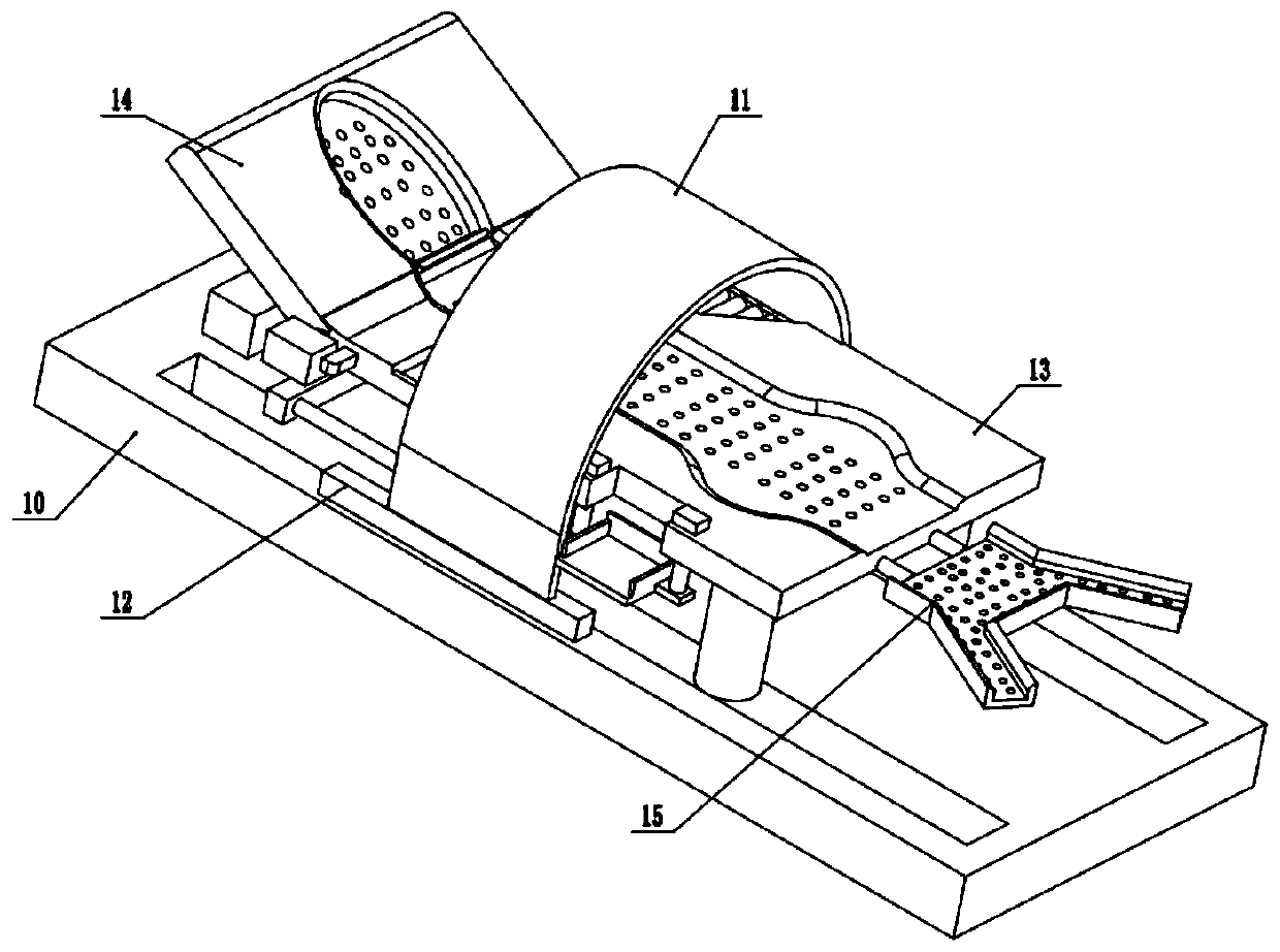
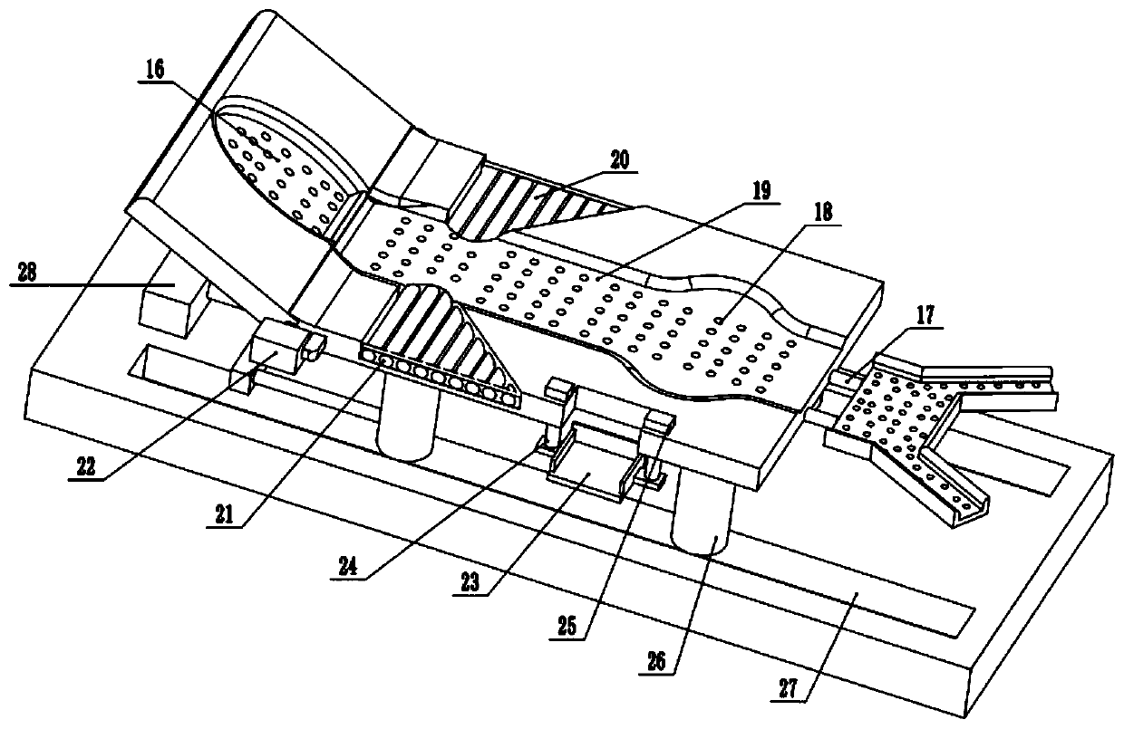
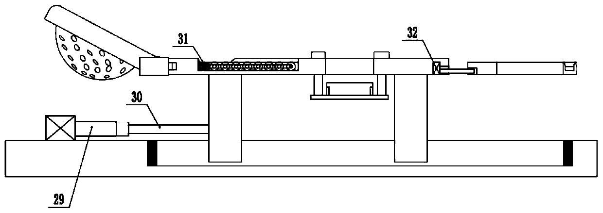
[0022] see Figure 1-3 , a device for adjusting the patient's body position for medical CT scans, including a base 10, a CT body 11, and an electric moving track 12; the base 10 is set in a rectangular plate-like structure, and two sets of chute slots are provided on the upper, front, and rear sides of the base 10. 27. Two groups of slide bars 26 are slidingly connected to the inside of the chute 27, and a group of lying beds 13 are installed on the top of the slide bars 26, and crash pads are fixedly installed at the left and right ends of the inside of the chute 27. The left side of the front and rear two groups of slide bars 26 located on the left side is jointly connected with a group of connecting frame 30 in a U-shaped structure, the middle part of the left side wall of the connecting frame 30 is connected with a horizontal piston rod 29 to the left, and the left end of the piston rod 29 is arranged There is a first cylinder 28 whose bottom is fixed on the upper surface ...

Embodiment 2

[0028] On the basis of Embodiment 1, the inside of the head groove 16, the lying bed 13, and the footboard 15 are all provided with several groups of ventilation holes 18 that penetrate up and down. 15 The air flow at the upper and lower positions prevents the patient from producing sweat and affecting the comfort level because the lower side of the body cannot touch the cold air when the patient is scanning for a long time.


PUM


Abstract

The invention relates to the technical field of medical instruments and discloses a patient body position adjusting device for scanning of a medical CT machine. The device comprises a base, a CT machine body and an electric moving track; two groups of sliding chutes are respectively and inwards arranged at the front side and the rear side of the upper part of the base, two groups of sliding rods are connected to the interior of the sliding chutes in a sliding manner, the tops of the sliding rods are jointly provided with a group of lying beds, the left side end of each lying bed is rotatably connected to a pillow plate through a rotating shaft, and a group of first rotating motors are rotatably connected to the rear end of the rotating shaft; two groups of telescopic rods are telescopically and inwards connected to the middle part of the right side wall of each lying bed, and the right ends of the telescopic rods are fixedly provided with a group of foot plates; and the right parts ofthe rear side walls of the lying beds are downwards connected to a group of lifting plates through a left group and a right group of lifting rods. The device has the advantages that the positions of the head, arms and feet of a patient are automatically adjusted through external electric control, the electric control assistance is realized through an upper lying bed and a lower lying bed, and thedevice has extremely high integral automation degree, is convenient to adjustment of the body position of the patient, and has higher use value.

Description

technical field [0001] The invention relates to the technical field of medical equipment, in particular to a device for adjusting a patient's body position for scanning a medical CT machine. Background technique [0002] CT is the biggest breakthrough in X-ray diagnosis since Roentgen discovered X-ray in 1895. It is the product of the combination of modern computer control technology and X-ray examination photography technology. CT was successfully developed in 1971. It was first used for the diagnosis of cranial brain diseases, and then expanded to the whole body examination in 1976. It is a great revolution of X-ray in radiology. [0003] The Chinese patent (notification number: CN 204500753 U, announcement date: 2015.07.29) discloses a patient position adjustment device for a medical CT machine, and specifically relates to a patient position adjustment device that cooperates with a CT machine. Including the turnover plate, on the turnover plate, there is a human body gro...

Claims


Application Information

Patent Timeline
IPC IPC(8): A61B6/04A61B6/03
CPCA61B6/032A61B6/0407
Inventor 时强王充强夏玲朱建忠
Owner THE SECOND AFFILIATED HOSPITAL OF SHANDONG FIRST MEDICAL UNIV
Why Eureka
Try Eureka